M1 DDS Controller
- M1 DDS Controller Kit
Description:
Updated! June 2022 - M1 DDS Controller Rev1.2
Block Diagram:
Updated! Dec 15 - M1 DDS Controller Rev1.2
Notes:
Updated! Dec 15 - EME190 PIC18F4520 Controller Board:
- EME189 Encoder Board:
- EME187 Logic Board:
- M1-DDS Software:
Updated! Apr 16 - Kit Constructors Alert:
- What Components are
required:
Updated! June 2022
- Kit changes and
Updates:
Updated! Apr 18 - M1 Transceiver Web Page:
- Buy the M1 DDS Controller Kit:
The M1 DDS Controller was designed to suit the M1 Transceiver project, and uses a Micro-controller with modified HF-DDS software that emulates a Yaesu FT817 transceiver, and with the logic interface is ideal for controlling many of the functions that are commonly used in radio receiver or transceiver designs. The Micro controller board has the option to connect an optional USB to serial data module so that it can be controlled using Ham Radio Deluxe software.
The complete M1 DDS Controller consists of a number of boards and components that are available as a complete Kit, or separately from Mini-Kits. A EME190 PIC 18F4520 Controller, EME189 Encoder Board, and EME187 Logic Boards are used along with various other hardware that includes a 16x2 LCD display and 4x4 numeric keypad. The M1 DDS controller can be used with either the EME165 AD9951, AD9954, or AD9850/51 DDS modules. The AD9851 is only a 10 bit DAC and does produce a few high level audible spurs that could sit right on commonly used frequencies. For a high performance receiver only the 14 bit AD9951/54 DDS should be considered. Software after version 1L now allows the use of Optical Encoder for smooth tuning.
The complete M1 DDS Controller Kit is for experienced constructors that already have some experience with soldering SMD components. This Kit may be a challenge for some with soldering of some of the SMD components mainly on the DDS board. Mini-Kits does offer pre-fitting of some of the very fine pitched Integrated circuits on the boards that are generally difficult for most constructors. Most wiring is now very easy due to the use of ICD headers and ribbon cable, but there are a few 2.54mm headers that use pins that need to be either crimped or soldered.
The DDS VFO frequency range required by the M1 Transceiver which
has a 9MHz IF, is 9 to 39MHz to cover a 0 to 30MHz frequency range.
The AD9851 or AD9951/54 DDS board all cover the required frequency
range, but due to the AD9851 being only a 10 bit A-D, the low level
birdies generated by the DDS can be very weakly heard on the higher
HF bands when atmospheric noise is low. So it is suggested that for
higher performance applications that the AD9951/54 14 bit DDS boards
be used, as the strongest birdies from the 14 bit chips are more
than 60db down. For use on the lower frequency bands under 10MHz,
the AD9851 board has been proven to work very well and birdies are
mostly under the noise floor.
The M1-DDS software has been developed from the original HF-DDS software to specifically suit the M1 Transceiver. Many of the functions and settings are exactly the same as the HF-DDS version, and can be used with both the EME150 and EME190 PIC controller boards.
Please refer to the M1-DDS Software documentation for further information.
All Software settings can be changed in the menu setting screens that are displayed on the LCD module. The keypad connected to the EME190 controller board along with the rotary encoder are used to change and memorize the menu settings into the EEprom. No reprogramming of the PIC with a computer is required.
Below are the standard specifications for the software supplied by Mini-Kits. The M1-DDS Source code is not currently available for download as the cost to develop it was high. A programmed micro controller can only be obtained by purchasing the EME190 PIC Controller.
- Frequency Range: 5KHz to 70MHz ( AD9850/51 ), 5kHz to 160MHz ( AD9951/54 )
- Frequency Resolution: 10Hz steps RF and display readout.
- Frequency Steps: Variable 10Hz to 100MHz
- VFO: Includes A B, split RX/TX, RIT, repeater mode
-
Ver 1.L Added the Option to use an optional Optical Encoder for tuning and menu selection - Bands: 160M, 80M, 40M, 30M, 20M, 17M, 15M, 10M, 6M, FM, AIR, 2M, 70cm, Phantom
- Modes: AM, FM, DIG, PKT, LSB, USB, CW, CWR
-
Ver 1.L Added Mode Frequency Offset to allow frequency alignment of each mode to suit home brew Crystal Filters - Menu setting to hide bands or modes that are not required.
- Memories: up to 202 including 2 for memory scanning, 16 memory groups, memory text labeling.
- Display Offset: to suit zero I/F, or first I/F roofing filters up to 145MHz
- Display Divider: zero I/F, divide by 2 or 4
- Computer Interface: Optional USB to serial adaptor
- Software: uses a pre-programmed PIC18F4520 with boot loader and M1-DDS verX.X firmware. ( up datable via optional USB )
How To do Software Updates Download
AN851 Microchip Quick Programmer Software Download
Microchip Boot loader Fix for Windows 7 Download
Border Padding Fix to use Microchip Boot loader on Windows 7 to 10. Try using the Winaero Tweaker App
Latest Firmware Update UPDATE_M1_DDS_VER_1_M.hex Download 18/4/16
Please note: That software updates are done through the A6 connector on the EME190 board. A low cost USB to serial converter can be used to create a COM port on a PC to use with the Microchip Quick programmer software.
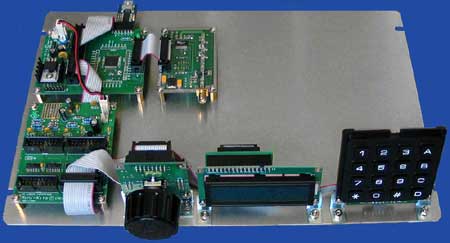
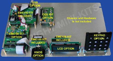
Shown below is the complete M1-DDS VFO Kit that is used by Mini-Kits for testing and development. The picture below shows what is included in the basic Kit, and does not include the aluminium chassis, hardware or DC power connector shown, all other parts shown are included. BUY THIS PRODUCT
- 1 x EME190 KIT ( PIC18F4520 PIC Controller Kit )
- 1 x EME189 KIT Encoder Board Kit
- 1 x EME188
KIT LCD Interface Kit
( suits standard LCD 4 and 5 modules ) M1-DDS KIT1
- 1 x EME198
KIT LCD Interface Kit
( suits jumbo size LCD 6 module ) M1-DDS KIT2
- 1 x M1-DDS Software Programmed
- 1 x 1 Metre 16 Way Ribbon Cable
- 1 x LCD4 ( Green/Black 16x2 LCD Module with Backlight )
- 1 x LCD5 ( Blue/White 16x2 LCD Module with Backlight )
- 1 x LCD6 ( Blue/White 16x2 Jumbo size LCD Module with Backlight )
- 1 x KEYPAD4 ( 16 Key Numeric 4x4 matrix )
- 1 x EME187 KIT M1 Logic Interface Board Kit
- 1 x KN-ELMA-020-7420 ( 45mm diameter knob and cap to suit the EC12E 6mm diameter D shaft encoder )
- 1 x USB-AD08 ( USB to Serial Adaptor )
- 1 x ENC-360-6 ( 360PPR Optical Encoder with a 6mm dia shaft)
- 1 x EME165-R2 KIT1 ( AD9951 DDS up to 175MHz Output, Very low spur output highly recommended )
1/ Almost all faults are due to poor soldering and or wiring with the IDC connectors. Using a multimeter check for continuity between the board connections through the IDC cabling as many issues are poor or incorrect.
2/ A problem occurred when the HF-DDS software when first powered up could not recognise the AD9954 chip. The fault was traced to a faulty TXB0108PWR level converter chip on the EME165 DDS board.
3/ No or low RF output from the AD9854 can be due to poor soldering of the chip to the board. Sometimes pressing down on the chip can increase the RF output indicating a poor solder joint on one of the pins.
4/ When turning the Rotary Encoder it either does not tune, or only tunes in one direction. Check that the diodes are correctly fitted on the EME189 control board. This can also be a problem with a faulty rotary encoder.
5/ LCD display backlight lights up but shows no characters. This was traced to poor soldering on a EME198 LCD interface board that had damaged a track from the IDC header connector to the 16 pin SIL connection. Check using a multimeter to confirm that you have no open circuit tracks.
6/ LCD display has no characters, or only shows square blocks on
the display top half. Please check that you have the wiring correct
from the EME189 board to the LCD module. Many have incorrectly wired
the LCD modules and damaged them.
7/ LCD display showing TX instead of RX. Check that there is +5vdc on RA4 TX_EN ( EME190 board ). There has been a report of damage to the RA4 input when +12vdc was accidentally connected.
8/ The LCD shows erratic characters like RX o.PU PKT SPL on the top row with 8 blank spaces underneath. When the rotary encoder is turned, the LCD then changes to RX o PL PKT SPL then to RX o.200 PKT SPL then counts down from 200. The menu functions also don't appear to work correctly, and the DDS output does not change when tuning. This is probably pins on the 24LC256 EEPROM that have not been fully soldered to the board, or been damaged when fitted.
9/ The keypad and rotary encoder intermittently doesn't function,
this has been traced to connection RC7 on the PIC18F4520 floating
and picking up noise. Tie the RC7 connection to +5vdc using a 4k7
resistor when an external USB to serial adapter is not connected to
the A6 connection on the board.
10/
- EME190 KIT PIC Controller KIT ( Link To Kit Web page )
- EME165-R2 KIT1 AD9951 DDS KIT ( Link To Kit Web page )


