VK5LO LEO Satellite Station

- LEO Satellite Status:
Updated March 25! - LEO Satellite Station:
Updated June 22! - Modified K3NG Rotator Software:
Updated Jan 24! - WSJT on the LEO Satellites:
Updated Jan 24! - Satellite Tracking Software:
Updated Jan 24! - WSJT on the LEO Satellites:
Updated Jan 24! - Starting out on the LEO Linear Satellites:
- 2m Antenna Construction:
- EME219 2m VHF Antenna Polarization Switch:
- 70cm Antenna Construction:
- EME219 70cm UHF Antenna Polarization Switch:
- EME216 4 Channel Wi-Fi Switch:
I will try to keep a reasonably updated list of Satellites that are
active and possibly failed and not heard in Australia below.
AO-7 Active very strong signals late afternoons. Australian stations should avoid using 432.150MHz for terrestrial communications due to interfering with the uplink.
AO-73 ( FUNcube1 ) Active very strong signals requires circular polarized Antennas due to fast spinning.
CAS-4A Failed power system.
CAS-4B Failed power system. Late afternoons it sometimes has just enough power to have a quick contact.
CAS-5A ( FO-118 ) Worked very well on all Transponders when first activated in 2023 for 2 weeks and not heard since. Have also monitored the beacon and GMSK and no signals heard. Unfortunately I never had a contact on this Satellite.
CAS-6 ( TO-108 ) Not heard for some time seems to have a failed power system.
CAS-9 ( XW-3 ) Not heard for some time. Have also monitored the beacon and GMSK and no signals heard.
FO29 ( JAS2 ) Not currently active over Australia due to its South to North path during the day. This Satellite is normally only tuned on on the weekends when it passes over Japan. March 25
GREENCUBE Not heard probably failed.
RS-44 Active very strong signals. Now shows some noise issues in the pass band that sounds like a noisy power supply.
SO-124 ( HADES-R ) Active but requires directional Antennas to successfully use it.
The description below is the actual Low Orbit Satellite, ( LEO ) station that has been constructed at Mini-Kits. So far the project has taken nearly 2 years to get to this stage after trying various antennas including, omni-directional verticals, double cross circular polarized omnis, and linear polarized yagi antennas. The outcome was that the downlink was very difficult to copy on omni-directional antennas, but much better on a directional yagi antenna. So a linear Alaskan Arrow yagi was purchased and the 2m and 70cm elements were placed on separate booms, and a Yaesu G-5500 rotator with cross boom was used for some time with good results. Looking at the design of the Arrow antennas it seemed that the station could be further improved by using modern computer designed antennas to reduce local noise. After some research it was decided to construct a DG7YBN design X-Pol yagi antenna for the 2m band, as these have a very clean pattern and should help with noise issues in the city. It was decided to try a 6x6 element which is more than adequate for the LEO Satellites, but with AO7 still in service it should give a bit more gain for the higher path loss. Initially tests were made on the 2m band downlink as this is more common with LEO Satellites, using a DG7YBN designed 6x6 element X-Pol yagi. The polarization was simply switched between the antennas using a relay but no circular polarization was yet available. The initial tests showed that the noise was much lower due to the cleaner pattern compared to the Arrow antennas. The EME218 polarization switch was then designed, prototyped, and tested on the antenna. A large difference was noted on 2m band downlink when going from horizontal to vertical, but not so much when using circular, although circular might help with not having to switch the polarization all the time over the Satellite pass. It was then decided to construct a DG7YBN 10x10 element X-Pol yagi for the 70cm band as the Russian RS-44 Satellite was just launched and used a 70cm downlink. The Satellite suffers from severe fading and the circular polarization did help make the downlink much easier to copy throughout the Satellite pass. A Mini-Kits EME216 4 Channel Wi-Fi switch is used to switch voltages to the VHF EME218 and UHF EME219 X-Pol polarization switches over a Wi-Fi link.
A Yaesu G-5500DC rotator is currently used and is controlled with a Arduino MEGA using modified K3NG rotator software. When researching rotator control, there was just too many options, and 99% were just too difficult to make work. With the K3NG rotator software it allows a low cost PWM driver module to be used on the MEGA to drive the motors directly from 24vdc. The K3NG software however is a very steep learning curve for the average Ham, as it requires many options to be set in the software for features and pins to suit an application. No LCD display or switches are really required as I was going to use SATPC32 software with RS232A to control the MEGA. PSTRotator software which is very good value and works well, will also work with the K3NG software for testing or when using the antenna system for non Satellite use. The controller uses a HC-05 blue tooth link to a computer in the shack that runs PSTRotator on a IC-9700.
The Antenna cables are all low loss CNT-240 which allows them to be easily routed and low weight, and for the best performance with strong signal handling, Mini-Kits 2m and 70cm low noise masthead preamps are used instead of the internal IC-9700 Pre-amps. The Pre-amplifiers were required due to the long 28 metre coaxial cable runs, but should not be required if cable runs are short and low loss. The external Pre-amplifiers may also help to protect the IC-9700 from lightning damage to the front end.
- DG7YBN Low Noise Yagi Website: Hartmut has done some excellent work here, highly recommended.
- DG7YBN 6x6 Element X-Pol: Download the Antenna Dimensions for 145.5MHz
- DG7YBN 10x10 Element X-Pol H Plane:
Download the H Plane Antenna Dimensions for 435MHz - DG7YBN 10x10 Element X-Pol V Plane:
Download the V Plane Antenna Dimensions for 435MHz - Download the Arduino
Rotator Controller Circuit Diagram Rev1.0:
- Download the Arduino
Rotator Controller Circuit Diagram Rev1.1:
NEW Updated Jan 24! - Download the Pre-Configured
K3NG Rotator Software:
NEW! - Settings for the Mini-Kits
modified K3NG Software:
NEW! - Mini-Kits modified K3NG Quick
Start Guide:
NEW!
 This picture shows the completed LEO Satellite Antenna system installed on a Yaesu G-5500DC rotator and 3.5m 50mm aluminium pole. The coaxial cables are routed out the back of the Antenna and held in place with an insulated conduit before looping around the rotator. This allows full azimuth and 180 degree elevation rotation without damaging the cables.
 Another picture showing the cabling from the X-Pol 2m and 70cm band antennas. The cross arm is constructed from two Trojan fibre glass shovels from Bunnings, and connected with Aluminium tubing.

 Picture showing how the 50mm aluminium mast was mounted. A 1m deep hole was dugout using a post hole digger, and plastic plumbing tube is then concreted into the hole allowing the mast to be easily removed.

 Another picture showing the completed mast with Satellite antennas mounted. The Antennas are around 3 metres above the ground which allows them to be easily worked on.

 Picture showing the X-Pol switches for the 2 and 70cm bands, and 70cm Pre-amplifier.

 Picture showing the K3NG Arduino rotator controller mounted on the mast. Some issues with the LM2596 switching power supply were found, causing minor interference on the 2 and 70cm bands. 43 material ferrites need to be fitted to most of the cables.

I have tried various Satellite tracking software and magic boxes with mixed results. None of them are 100% reliable while some also have limited functionality, and some are very old and have not had any major improvements for many years. Most issues that I have experienced are when using linear Satellites and the limited or no ability to adjust the uplink frequency XIT to net the downlink where other stations are calling. Some stations that have older transceivers successfully use the analogue RIT, but this becomes difficult on the IC-9700 due to it having digital RIT tuning and the software continually updating the doppler. I have put some comments below to what I have experienced.
The SatPC32 from
DK1TB does work quite well, but does have some minor annoyances when
used with an IC-9700. The main issue is the difficulty with tuning
of stations on receive especially when there are multiple stations
in a round table QSO. The software locks out the ability of using
the RIT control on the IC-9700. Other issues include, having to
manually set the doppler update speed, doppler tuning pausing when
there are voice announcements, and intermittent loss of com port
control to the rotator. Said that I had been using it for well over
12 months and had many contacts.
The current software being used is PSTRotator by Codrut Buda. The Rig control uses Omnirig and a special file for the IC-9700 has been created by Codrut making it a very slick operation. It can take some time to initially set it up the software which is quite complex to understand, but is very worthwhile. I have created a document with some of the settings required to make it work, along with a current Satellite list to suit which can be simply copied into the main PSTRotator programs folder.Multiple instances of this Softweare can also be setup to control other rotators for specific applications which makes it a real winner.
PSTRotator settings for
the IC-9700 and controlling of the K3NG Arduino Rotator controller
via a com port.
There is however some issues with the Doppler.sqf file that is
currently being supplied in the PSTRotator software. I have made
some changes to suit the current satellites and it is available here
Doppler.sqf Simply unzip the file and
drop it into the main software folder of PSTRotator.
PSTRotator Satellites1.txt ( has
the current operational Satellites to save you time entering them )
This may not work with all transceivers and has only been tested on
the IC-9700. Simply unzip the file and drop it into the main
software folder of PSTRotator.
Due to weak signal modes requiring high frequency stability less than 4Hz drift, the IC-9700 has been GPS locked with the GPS-9700. The IC-9700 can be setup to not only work with PSTRotator, but also WSJT at the same time, as it has two com ports on the same USB connector which are both required. I was able to setup two lots of WSJT, one on the TX side uplink, and on the downlink audio to confirm the tests. For more information download the document below.
Download WSJT on LEO Satellites document on how to get started with the settings using an IC-9700.
I hope to do more tests soon. I have done some tests on the CAS4 and RS44 Satellites using FT4, and it works perfectly showing less than 1Hz frequency drift on the downlink in WSJT. Tests using FT8 did not reliably work due to the longer time and the high Doppler of LEO Satellites, so only short transmission modes like FT4 can be used. The question now is do we allocate a frequency allocation for these modes somewhere near the bottom of the Transponders.
Recently January 2024, I have done some tests on AO-109. As the Satellite was approacing I did get a few FT4 decodes, but then as it passed above and through to LOS, I was no longer able to get any decodes. The FT4 signal on the waterfall indicated some type of frequency distortion which is probably an issue with the Satellite Antenna like multipath. FT4 tests on the AO-73 so far have been unsuccessful due to the high spinning of the Satellite even when using circular polarization.
Due to the high doppler with LEO satellites when at high angles, it can be difficult have your station on frequency. This can be due to a number of factors including, the software, frequency stability, and computer clock timing.
Not all software works 100% with controlling a Transceivers frequency for doppler. Add to that the requirement to use an RIT on receive, especially if there is a round table of stations. Tests using an IC-9700 indicate that turning the main VFO to tune stations using either SatPC32 or PST Rotator, can cause the software to unlock the doppler tuning uplink TX frequency. The software really only works correctly when the tuning is done on the software screen, so it can take a station some time to resolve another station that is on a different frequency. If you are using an IC-9700 then frequency stability can be an issue especially on 70cm's. It is recommended to frequency lock the Transceiver with an external reference or GPS locking.
I have listed some ideas below which may help when first working LEO SSB Satellites.
-
Trying to work the LEO Satellites without tracking software is a waste of time, and you will just be chasing yourself all over the Satellites passband causing interference to other Stations. The Satellite tracking in the Icom IC-9700 menu does not work and should not be used.
-
First make sure that your computer clock is locked to software like dimension 4, and that you have the latest Keps and your grid locator is accurate. Even a one second inaccuracy can cause you to be 100Hz off frequency. Add to that an incorrectly entered grid locator in the tracking software and it becomes very difficult. In theory, if two stations are using the latest Keps, and their computer clocks are locked, and the grid locator is accurate, then they should be both on frequency and easily able to have a contact.
-
It is recommended that when you first start using Satellites, that you experiment with first listening to the beacons, making sure that you are correctly tracking the frequency doppler throughout the pass. This will also help to determine if your downlink Antenna is suitable.
-
Then do some SSB experiments 10 to 15kHz away from the centre of the passband to see if you are on frequency. All Satellites will have some frequency changes due to temperature change with their local oscillator. It is recommended that if you edit your frequencies for a particular Satellite, that you only ever edit the uplink frequency. Do this by transmitting through the Satellite, and changing the up link frequency on the software screen until you are perfectly resolved. You can then edit the software file to update it. Many Software frequency lists can have incorrect frequencies, USB and LSB inverted, or have the tuning set incorrectly as inverted or normal. Regularly updated lists can be found here.
-
When calling on a satellite, make sure that you call for at least 15 seconds so that other stations have time to tune you in. Not all Transceivers can be easily tuned using the main VFO or RIT due to the software.
- If you use the RIT on your Transceiver, always make sure that you reset it after use.
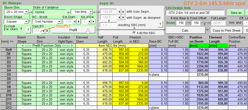
The 2m 145.5MHz Yagi antennas are mounted on the same boom in an X configuration with a 110mm offset between the two. As the antennas have an 110mm offset, one of the coaxial cables to the antenna closest to the incoming satellite signal will require an additional length to create a delay. This delay effectively lines up the antennas on the boom as if there was no offset between them. On a LEO satellite system using 180 degree elevation, typically 3m long cables will be required from the driven elements and for safely looping around the rotators to prevent damage. The extra cable required for the 110mm offset depends on the cable velocity factor, and for CNT-240 the VF = 0.83 which calculates to a coax length of 91.3mm, so make one of the cables 3.091 metres long.
The design uses 20x20mm ( or 19x19mm ) square boom and 6.35mm diameter aluminium tube for the elements. The elements are held in place with Stauff® 106-4-PP clamps using M6x30 SS Hex socket screws with M6 SS rivet nuts. The Balun is a 1/4 wavelength of RG142 coaxial cable cut and tested on a VNA with a FB31-480002 31 material ferrite bead for isolation. The ends of the coaxial cable are connected to the driven element halves using M3.7 Eyelets and M3x10mm SS screws, M3 SS nuts, and washers. The fancy 45 degree boom to cross boom slant polarization brackets are available from onwireless. The Female BNC connector is an Amphenol 112272 for RG-58 type cable that just fits onto the RG142 cable.
- DG7YBN Low Noise Yagi Website:
- DG7YBN 6x6 Element X-Pol: Download the Antenna Dimensions for 145.5MHz
- Buy a EME219 2m VHF X-Pol Switch:
REFERENCES:
1. Switching Four Polarizations on a 70cm Crossed Yagi by Domenico
Marini I8CVS, Amsat Journal
2. Antenna Circular Polarization by Mak SV1BSX
3. Simple Polarization Switching by SM5BSZ
4. How To Calibrate and Adjustable Polarization Antenna by SM5BSZ
 Mini-Kits constructed DG7YBN X-POL 6x6 element Antenna for 145.5MHz LEO Satellites. The offset between the antenna is 110mm so when using CNT-240 cable with a VF of 0.83, one needs to be 91.3mm longer than the other.

 Picture shows a close up of the dipoles using the Stauff insulators and 6.35mm aluminium tube. The cables are 1/4 wavelength long RG142 with 31 material ferrite beads for isolation.

 Mini-Kits constructed DG7YBN X-POL 6x6 element Antenna for 145.5MHz LEO Satellites. The offset between the antenna is 110mm so when using CNT-240 cable with a VF of 0.83, one needs to be 91.3mm longer than the other.

 Picture shows a close up of the EME218/219 2m band X-Pol switch. Cables are all CNT-240.

The 70cm 435MHz Yagi antennas are mounted on the same boom in an X configuration with a 260mm offset between the two. Please Note that the dimensions supplied by DG7YBN have an offset of 280mm, but this does not work due to the use of the Stauff clamps and clearance problems. I initially drilled all holes to suit the 280mm offset then had to turn around all the Stauff clamps 180 degrees on one yagi to get the required clearance. The Stauff clamps have a 20mm distance from the element to the mounting hole, so this is where the 280 to 260mm change is. As the antennas have an 260mm offset, one of the coaxial cables to the antenna closest to the incoming satellite signal will require an additional length to create a delay. This delay effectively lines up the antennas on the boom as if there was no offset between them. On a LEO satellite system using 180 degree elevation, typically 3m long cables will be required from the driven elements and for safely looping around the rotators to prevent damage. The extra cable required for the 260mm offset depends on the cable velocity factor, and for CNT-240 the VF = 0.83 which calculates to a coax length of 216mm, so make one of the cables 3.216 metres long.
The design uses 20x20mm ( or 19x19mm ) square boom and 6.35mm diameter aluminium tube for the elements. The elements are held in place with Stauff® 106-4-PP clamps using M6x30 SS Hex socket screws with M6 SS rivet nuts. The Balun is a 1/4 wavelength of RG142 coaxial cable cut and tested on a VNA with a FB31-480102 31 material ferrite bead for isolation. The ends of the coaxial cable are connected to the driven element halves using M3.7 Eyelets and M3x10mm SS screws, M3 SS nuts, and washers. The fancy 45 degree boom to cross boom slant polarization brackets are available from onwireless. The enclosure is a Bopla 03206000, and the M12 cable glands are 822-9739 from RS Components. The Female BNC connector is an Amphenol 112272 for RG-58 type cable that just fits onto the RG142 cable.
- DG7YBN Low Noise Yagi Website:
- DG7YBN 10x10 Element X-Pol H Plane:
Download the H Plane Antenna Dimensions for 435MHz - DG7YBN 10x10 Element X-Pol V Plane:
Download the V Plane Antenna Dimensions for 435MHz - Buy a EME219 70cm UHF X-Pol Switch:
REFERENCES:
1. Switching Four Polarizations on a 70cm Crossed Yagi by Domenico
Marini I8CVS, Amsat Journal
2. Antenna Circular Polarization by Mak SV1BSX
3. Simple Polarization Switching by SM5BSZ
4. How To Calibrate and Adjustable Polarization Antenna by SM5BSZ
 Mini-Kits constructed DG7YBN X-POL 10x10 element Antenna for 435MHz LEO Satellites. The offset between the antenna is 260mm so when using CNT-240 cable with a VF of 0.83, one needs to be 216mm longer than the other.

 Picture shows a close up of the dipoles using the Stauff insulators and 6.35mm aluminium tube. The cables are 1/4 wavelength long RG142 with 31 material ferrite beads for isolation.

 Picture shows a Bopla 03206000 ABS enclosure used to mount the driven element to the boom. The cable glands are M12 IP68 Nylon. The ferrite is a 31 material 2631480102

 This picture shows the mounting of the BNC connector to the boom. An Amphenol 112272 BNC female connector for RG58 cable just fitted onto the RG142 cable.

 This picture shows cabling to the EME219 70cm UHF X-Pol switch

 This picture shows the EME216 Wi-Fi module that controls the switching of both the EME218/219 2M VHF and EME219 70cm UHF X-Pol switches.
