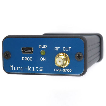
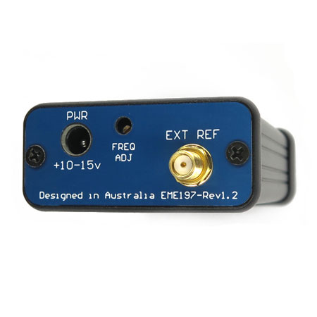
GPS-9700 Locked Frequency Source
- GPS-9700 Description:
Updated July 2022! - GPS-9700 Application Block
- Kit Constructors Alert:
- GPS-9700 Kit Notes:
- LZ2WSG Programming Software:
- IC-9700 Reference Adjustment:
- Installing the Coupler Board IC-9700
- IC-9700 / GPS-9700 Phase Noise Tests:
- 23cm Band WSPR Tests:
- Mounting into a Hammond 1455C Enclosure:
- Kit Changes and Updates:
Updated Nov 2024! - Buy this Product:
The GPS-9700 is the first original external signal source that was developed by VK5EME and VK5WA, in March 2019 for the Icom IC-9700 Transceiver to stabilize frequency when using narrow band weak signal modes. Much of the design work for mode locking the IC-9700 TCXO and coupler was copied by others without any acknowledgement of the original design idea. The reverse DDS design idea is owned by G4JNT, and was used in this design for the PLL phase comparator.
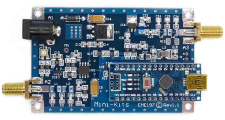
The GPS-9700 can be used with or without an external 10MHz reference input to make a IC-9700 frequency stable to less than 1Hz on all weak signal modes including on the 23cm band. For high frequency accuracy especially when using Transverters for the high microwave bands, it is suggested that the GPS-9700 is locked to a high quality external GPS derived 10MHz frequency reference. The design incorporates a 0.28ppm low phase noise 49.152MHz Voltage Controlled Temperature Controlled Crystal Oscillator ( VCTCXO ) reference which is amplified, and filtered to produce a very clean RF output. The signal is then injected into the IC-9700’s internal 49.152MHz frequency reference using a small coupler PC board to mode lock the frequency.
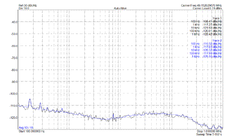
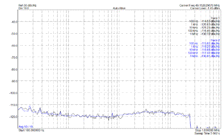
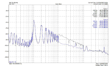
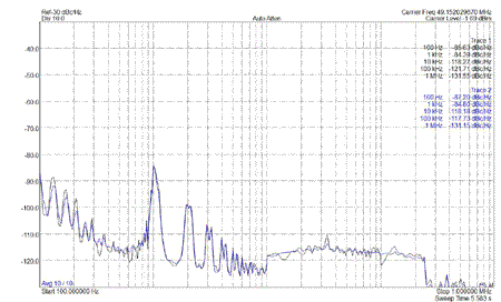
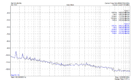
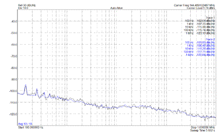
Tests using a Signal Hound analyzer locked to the Trimble GPS reference indicate that the phase noise when using the GPS-9700 is identical to the Radio on its own.
Due to the frequency stability of the IC-9700, the Ref Adjustment procedure will be required at times due to seasonal changes of temperature in many parts of the globe. I suspect that the TCXO Icom used in the IC-9700 is not very good, as many other TCXO types have a much larger footprint due to the components required for stability. In southern Australia have had to realign the Ref Adjustment a number of times throughout the year, as temperatures can range from a couple degrees on winter nights to 40+ on a summer day.
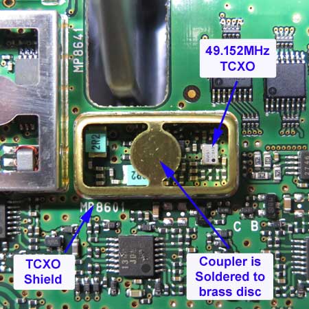
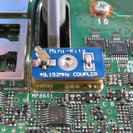
The use of this product does require removal of the Icom IC-9700 bottom cover and replacement of a cable and soldering of the small coupler PC board over the brass TCXO compartment. This should not affect Icom warrantee as No modifications are required to the Transceiver that could damage it. This also means that when the GPS-9700 is not used, the Transceiver will still function the same as from the factory and be locked to its internal TCXO. The use of the GPS-9700 however will not allow the automatic 10MHz calibration to work as the SMA to IPX cable is replaced and used with the coupler board, but this should not be an issue as manual calibration is still available.
1/ There can be an issue that the VCTCXO module has no output due to it not being successfully soldered to the board. I have come across this numerous times and it is difficult to flow solder under the device, so any intermittent or no output is probably due to soldering.
2/ Adjusting the 10MHz GPS drive level input to the GPS-9700 will affect the phase noise. It is best to use the lowest drive possible for lock, and then increase the level by 5dB for good locking. Some products have now been supplied with the NXP SA612AN which appears to require less GPS drive signal, and tests have shown that -10 to -20dB input is ideal for the lowest phase noise.
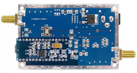
The pictures below are a final revision so should be carefully followed in construction. Probably the only really difficult part is the fitting of the AD9835. It is very important that the Kit construction notes are followed very carefully with regards to initial testing of the 5v regulator before increasing the voltage to the board. BUY THIS PRODUCT
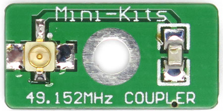
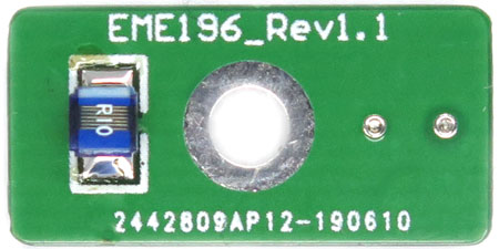
The pictures below show the coupler board with components fitted to suit the IC-9700. Care should be taken when fitting the small IPX connector as it has to be mounted so that the centre pins connection on the underside of the connector is soldered to the PC board strip line track. When fitting the board to the IC-9700, care should be taken when dismantling the transceivers bottom cover and soldering the board into place. The SMA connector cable on the rear of the Transceiver is removed carefully replaced with a longer cable which is connected to the coupler board instead of the Transceivers main board. This means that the automatic 10MHz calibration will no longer work but it is not required when using the GPS-9700.
This open source Arduino software has been written by LZ2WSG to program a AD9835 DDS to a single frequency.
The Programming LZ2WSG software can be used to program the Arduino Nano for a single frequency for the AD9835.
- With the GPS-9700 disconnected, Tune the IC-9700 to a GPS locked beacon and set the mode to CW. Changing between CW and CWR should give the same tone frequency from the speaker if the IC-9700 is on frequency. Adjust the IC-9700 REF Adjust fine to mid setting, and adjust the course until the CW and CWR tones match.
-
Connect the GPS locked GPS-9700 to the coupler board and check that the tones still match for both CW and CWR. Removing and reconnecting the external GPS signal will cause a slight tone glitch which indicates that the GPS-9700 is working. Taking note of where the Ref freq is set, if you now adjust the REF freq up and down, a frequency wobble will be heard at each extreme which indicates that the GPS-9700 is trying to lock the IC-9700. This is a good indication that the GPS-9700 is working correctly. Return the Ref freq to where it was set.
-
There are issues with the IC-9700 frequency stability between summer and winter temperatures. This can cause the audio to sound warbly as the GPS- 9700 is unable to pull the IC-9700 onto frequency. This will require the IC-9700 Ref Adjustment to be checked on a GPS locked beacon a number of times throughout the year.
The module board is designed to be fitted into a Hammond 1455C extruded aluminium enclosure. The enclosure helps to stabilize the free running frequency of the VCTCXO by protecting it from environmental temperature changes. Assembly is quite straight forward but you will require another SMA washer to be fitted onto the RF OUT connector as a spacer before the front panel is fitted. The LED should also be fitted after the front panel has been fitted as it makes it much easier to bent the leads to fit the board before soldering into place.
1/ One of the original prototypes could no longer be adjusted onto 49.152MHz, and was due to the TCXO aging over time and being low in frequency. This potentially could be an issue with TCXO's in other products also which may need a resistor changed. The fix was to replace R9 from a 1K1 to a 1K5. This then allowed the trimpot to be in the centre again for 49.152MHz. The value might be slightly different depending on the aging of each TCXO. The voltage divider values made up of R8, VR1 and R9 was deliberately chosen to make the adjustment easier so has a very limited frequency range.
2/ Rev 1.2 products after February 2024 have been changed to fix a long term issue with clock level to the AD9835 DDS. This causes no 10MHz output from the DDS chip, and the AD9835 has always thought to have been from bad batches as replacing it often fixed the problem. R17 has been changed from a 2k2 to 1k8 which will now produces a reliable 3.2V p-p clock signal on pin6 of the DDS chip. A number of production builds have been tested and fix the problem for good.
3/ The original batch of Kits tested used a Philips SA612AN which has now changed to the NXP SA612AN. It appears that the optimum 10MHz GPS input drive may need to be reduced by up to 20dB when using the NXP chip version possibly due to higher gain in the oscillator amplifier. So the recommended input for the NXP chip version is -10 to -20dBm. The best way to determine this is to vary the 10MHz input level until there is lock and then reduce attenuation by a further 5dB for good lock. The lower the input with lock then gives the lowest phase noise at 49.152MHz.
4/ Low or No RF output at 49.152MHz can be due to the VCTCXO IC5 not being fully soldered to the board. Resolder the connections carefully ensuring that solder flows under the pads. his can be very difficult to do and pre tinning of the component pads and solder flux is normally required for reliable connections.
5. There are issues with the IC-9700 frequency stability changing between summer and winter temperatures. This can cause the audio to sound warbly as the GPS- 9700 is unable to pull the IC-9700 onto frequency. The IC-9700 TCXO adjustment will have to be performed a number of times throughout the year especially in temperate climates like Australia.

