EME175 Butler Oscillator Kits
- EME175 Version1 Description:
Updated! June 2022 - Kit Constructors Alert:
- EME175 Kit Construction Notes:
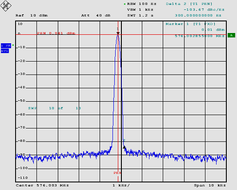
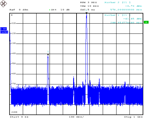
Updated! Jan 2019 - EME175 Kit Performance Tests:
- Enclosure Mounting:
- Oscillator Design:
- Optional EME177-R2 Oscillator Heater Kit:
- Kit changes and Updates:
Updated! Mar 2019
The Mini-Kits 400 to 540MHz Butler Oscillator is a redesign of the popular EME65 Kit that we sold for over 10 years, and is suitable for use with Transverters, Receive converters and frequency multipliers. Many hours were spend with the help from Kevin ZL1UJG, including input from others to evaluate the EME65 Kit to improve the performance, and update the design. Improvements have been made to lower the power supply and oscillator phase noise, including heat sinking and insulating requirements to suit a temperature controlled heater. Optional components can be fitted to allow for phase locking the oscillator from a GPS PLL reference. The oscillator will provide a stable +7dBm output in the 400 to 540MHz range suitable for Transverters and RX Converters from the UHF to Microwave bands. The Optional EME177 Oscillator Heater Kit has been designed to suit the EME175 Kit, and ideal for use with high temperature crystal to obtain stability.
1/ If the oscillator won't start change the 470ohm resistor on the emitter of TR1 to a 1K. Also make sure that the capacitor that couples the collector of TR1 to the base of TR2 is a 10pF leaded type monolithic or ceramic capacitor, as SMD types will not work. It is unknown why a SMD type won't work but it could be something like inductance in the leaded type.
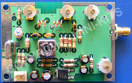
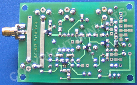
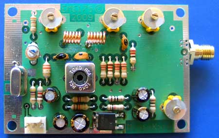
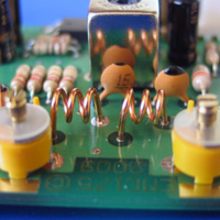
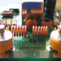
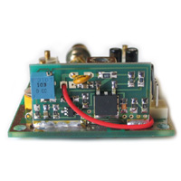
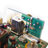
The images below show the different versions of the Kit. Take note how the coils are wound, as many tune up problems can be traced to the coils being incorrectly wound. The trimmer capacitor settings show the positions when using the crystal mentioned below.
The Crystals case must be connected to the top of the board with a wire link for stability. An optional 50 degree C PTC Heater can be used with 50 degree cut crystals for temperature stability. The PTC is fitted up against the crystal, and a short length of heat shrink is used to hold it into place against the crystal.
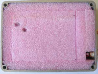
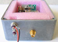
The main things to remember when mounting the oscillator into an enclosure is that it needs to have insulation to stop temperature changes from affecting the frequency. The easiest way it to use polystyrene foam inside the enclosure.
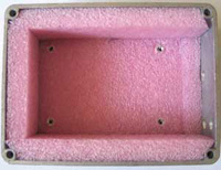
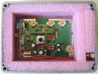
The recommended enclosure used below is a Hammond 1590S ( 110x82x40mm ), which allows enough room to line the enclosure in 10mm polystyrene insulation. The Pink foam shown below should not be used, as the density is too high so thermally it is not very good. I highly recommend that you use 10mm low density white polystyrene foam in the box, and if you fit it very tightly, then it is a very good insulator. The PC board is mounted to the bottom of the enclosure using 10mm metal spacers. The board is insulated from the spacers using plastic stepped transistor insulators to reduce heat transfer loss from the board to the enclosure. A piece of polystyrene could also be used across the middle of the enclosure to reduce the thermal gradient in the box. This may improve the temperature stability by not having as much air inside the box around the main oscillator section to keep at a constant temperature. The die cast enclosure can be obtained from RS Components part # 3642269. Expensive Feed through capacitors have been used for +12 volts and the Heater output temperature voltage, although you may want to use something more cost effective.
References:
These References are highly recommended for those that want to learn more about Crystals and Oscillator design.
1/ Crystal Quartz Resonators Ham Radio Magazine February 1986
2/ Crystals Made Clear Part 1 Electronics World September 1999
3/ Crystals Made Clear Part 2, Electronics World October 1999
4/ Solutions For Stable and Precise Microwave Frequency Generation, VHF Communications 2/2005
5/ Low Noise VHF Crystal Oscillators DK4XP, VHF Communications 4/2000
7/ www.vectron.com/products/ocxo/ocxos.htm
8/ https://wenzel.com/technical-resources/
The stability of the Oscillator can be calculated by testing the frequency drift in Hz. Then by entering the figures in to the calculator on SiTime the stability in PPM can be calculated.
1/ There can be a number of things that can cause the oscillator to not start, and this can vary depending on the crystal frequency and the surrounding component values used. Some Kits may need the 470ohm resistor on the emitter of TR1 to be changed to a 1K for more reliable oscillator starting, but this is not always the case. You normally have to experiment with the capacitor across L2 to make sure that it is resonant near the crystals frequency. Also the 10pF that couples the collector of TR1 to the base of TR1 seems to cause the oscillator to not start at times when a SMD type is used. When a 10pF leaded type monolithic or ceramic NPO capacitor is used, then this might then allow the oscillator to reliably start.
2/ For Kits after February 2016, the BFR92A Transistors have been changed to BFU530A as the BFR92A are no longer manufactured. No other changes are required as the BFR530A is equivalent.
3/ Low -10dBm output power, or the oscillator wont work. BC849C transistor TR4 S/C base emitter.
4/ Low output power or cannot tune output trimmers TC4 and TC5. Check 100pF chip capacitors for either cracks or not soldered both sides.
1/ It has been difficult to test for oscillator frequency stability using the EME177 Heater due to the Aging of the HY-Q crystals. Initial frequencies of most Crystals have been around 250Hz high at the fundamental using a 10pF NPO across the 10pF Murata trimmer capacitor 1/2 mesh. Most have also been found to Age downwards in a rapid rate of around 80Hz per day in the first couple weeks, and still around 40Hz per day after 3 weeks.
2/ Only one Crystal was found to go up in frequency by around 20Hz before reversing and Aging downwards. It was suspected that this was due to contamination on the crystal that slowly disappears with vibration. Frequency jumps were also recorded as the frequency increased.
3/ It is recommended that you at least run the oscillator for a number of weeks before even considering testing frequency stability and trying to accurately align the frequency. When you are sure that the aging has decreased, then you can try and set the frequency more accurately. I am still unsure what capacitor value is required across the 10pF Murata trimmer capacitor, and this could vary with crystals. Some 96MHz crystals that were tested from the same manufactured batch, were over 500kHz different in frequency. Initial tests used a 10pF NPO, but with one that has aged over 3 weeks has now been changed from 10pF to 4p7 to bring it up onto frequency.

