EME85 AD9851 DDS KIT

- EME85 DDS Kit Description:
Updated Jan22 - Download the Complete EME85 Kit Notes:
- Original Software Version:
- Kit Changes and Updates:
- Buy the DDS Ver2.3 Software:
There were many minor changes to the EME85 PC board which was first produced in the late 1990's. Original boards had no plated through holes or solder masks, and newer versions of the boards were professionally made and have suffixes of D, E, and F after 2002. The basic layout of the board never changed until 2009 when it was completely updated to the EME167 KIT.
 Above shows a D suffix version of the board that had solder plating over the copper for some protection.
 Above shows a complete D suffix version of the Kit that Used the EME129 Control Board 2
1/ Any problems associated with the PIC16F628 chip can normally be confirmed by checking that it lights up the LCD display correctly, and; that the control board works correctly. Most problems are either incorrect wiring between the EME85 board and LCD module, or simply the contrast trim-pot on the EME85 board not being set. To test the LCD display without the PIC chip just turn up the contrast trim-pot until all 16 x 2 segments light up.The wiring from the EME85 board ( DDS only Kit ,) or EME159 ( Sweep Kit ) have some wires that are not directly connected inline with the ribbon cable and cross over others. So please check this carefully as its very easy to make mistakes. I recommend using the LCD module data sheet and the PC board overlay diagram for either the EME85 or EME159 kits and carefully understand the wiring. This confirms that the LCD module is probably ok. This however will not test the data and clock signals to the DDS chip that can be confirmed with an oscilloscope. Most problems with the LCD not lighting up are due to wiring errors and not the DDS chip. The DDS chip will not prevent the PIC16F628 from working the LCD display.
2/ If you are getting erratic letters and numbers, ( Garbage ) on the LCD, disconnect everything from the DDS board excluding the LCD first. If the LCD is still showing the same garbage on the display, then the software in the PIC is probably corrupted and needs reprogramming.
3/ If you have problems with the LCD not lighting up, or the control board not working and want to confirm if the DDS board is OK, then the EME85 board can be tested by disconnecting the LCD and control board connections and turning on the DDS. The PIC16F628 supplied with Kits is programmed for a 10.5MHz output that can be checked on a suitable HF receiver. This is only the case if you are using a 30MHz xtal module and the menu settings have not been changed.
4/ Some pins around the AD9851 chip may appear to be shorted with solder. This is quite ok as the pins are all ground connections and are connected underneath the chip. If you have problems with the DDS chip not producing any output then please check for un-solderd pins.
5/ When using the DDS as a local oscillator for a receiver or transmitter, a simple one to one PLL, ( phase locked loop ) circuit with VCO, ( voltage controlled oscillator ) may be required. The DDS used on its own may produce an approximate 1Khz audio tone to be heard from the receivers speaker. This is due to the DDS output being rather complex with the frequencies that are produced. Most modern Transceivers that use a DDS, use one as a reference oscillator on a PLL. A simple 1MHz high pass, or bandpass filter on the output of the DDS may fix this problem.
6/ A MAR-6 now replaces the ERA-5 in new Kits. It has better low frequency gain compared to the ERA-5 and is much lower cost. The Standard bias on the MAR-6 is normally 16mA which would give us gain compression due to being overdriven by the AD9850/51 output. If we raise the bias the MAR-6 to 30mA using a 270ohm resistor, we raise the P1db from +3dBm to +10dBm output which is still under the maximum recommended 50mA. Thanks to Lim Chin-Leong 9W2LC for this idea. All later Kits are fitted with the MAR6 and 270ohm resistor.
7/ There has been a report of the calibration menu settings not being able to be set. Please disconnect the 4 x 3 Keypad and see if the menu works ok. A faulty keypad with leakage was found to have caused the fault.
1/ If you are using a AD9850 chip you need to program the PIC with the DDS_9850.HEX file contained in the dd_synth_v21 ZIP software file. The menu setting to set for either a AD9850 or 51 chip was disabled in Version 2.10. This was to fix the unexpected problem of possibly destroying an AD9850 chip if you have set the PIC software for a x6 multiplier which the 9850 does not have.
2/; If you have one of the older Kits with software versions 1.50 or older, then it is best to upgrade the software and use the later EME129 control board kit. We are no longer supporting the older software versions so any problems associated with the older software are no longer listed on the web site.
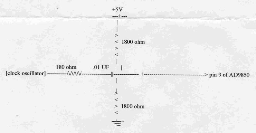
3/ One fault that has been reported for this Kit is low output from the clock module, causing erratic frequency jumping. The problem seems to be the output from the clock module being low, and can be fixed by biasing the clock input pin9 of the AD9850 to 2.5v. Refer to the diagram for modification. Thanks to Kam Ng for this one. Another remedy for this could be to change to a different brand of clock module. One brand was found to not quite reach 0v on the low clock cycle.
4/ Erratic Frequency jumping when tuning was found to be a crook PIC16F84 microprocessor. Reprogramming the PIC did not fix the problem, it had to be replaced.
5/ Low output from the ERA5 amplifier could be due to the 150ohm resistors leg on the ERA side being soldered to the bottom earth of the PC Board. This pad should be recessed on the ground plane side, or the leg of the resistor should only be soldered to the top track side of the board.
6/ For any other problems, check that there is no copper tracking between tracks on the PC board. This has been a common problem around the AD9851 chip. Some pins including Pins 1+2 may have a solder bridge connecting them, along with Pins 26, 27, and 28. This is quite OK, as they are connected by tracks on the PC board and are shown connected on the circuit diagram. Check against the circuit diagram.
7/ For incorrect output frequency compared to what the LCD display says, Please go to the CAL menu first and check the settings for the Xtal Oscillator Module that you are using.
8/ For no or low +5 volts on the AD9850/51 DDS IC check that the +ve connection on the 10uF capacitor on the output of the 7805T regulator, is soldered on both sides of the board. The connection is a feed through from one side of the board to the other.