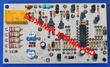
EME66 Sequencer Kit
- EME66 Sequencer Description:
Updated! June 2022 - Download the complete Kit Notes:
- Kit changes and Updates:
- Buy the replacement EME166 Kit:
The EME66 Sequencer was one of the most popular Kits that we have ever sold. It has been designed to fully control a Transverter and various other components like, antenna relays, power amplifiers, and Pre-amplifiers etc. The Sequencer has 3 delayed TX output switching voltages, and a single RX output switched voltage. The Sequencer has the option of either RF or voltage RX to TX switching from a 28-430MHz Transceiver, and can handle up to 3W max input. TX output power from the sequencer can be adjusted down to 0dBm ( 1mW ), with 3Watts input for driving a Transverters mixer direct. The receive I/F signal path has an adjustable trim-pot attenuator to set the maximum gain required for the receive conversion and transceiver used.
1/ Current Kits are supplied with 3x BC640 and 1x TIP32/42 transistors. Only low current transistors are really required for RX power and TX exciter stages.The higher current TIP32/42 can be used to drive relays or a Power Amplifier.In Kits after March 2011, 3x 470ohm resistors have been supplied as in the original Kit. If you find that you are unable to make one of the transistors switch loads like relays etc, the 470ohm base bias resistor to that transistor can be replaced with a 220 to 270ohm 0.6w metal film type. The resistor should be positioned around 5mm off the top of the board due to the higher dissipation.
2/ A modification was done to Kits after 2001, where the base bias resistors for the BC640/TIP32/42 Transistors were changed from 470ohm to 220ohm. This was to increase the base current to reliably switch multiple relays. This was found to be required when driving 2 relays in parallel besides a TX exciter stage. The only problem is that the dissipation of these resistors can exceed their 1/4 watt rating and should either be decreased to the original 470ohm value for low current switching, or the resistors changed to 0.6W metal film types. Heat sinking of the transistors was found to not be required in all Transverter prototypes so far.
3/ After testing of the TX Delay circuit is was found to not have a long enough hang time on SSB when using the RF sensed switching. This causes the sequencer to go back to RX mode in between words on SSB. The 10uF / 10k ohm resistor combination was designed to do this job, but for some unknown reason it no longer works. I am unsure if something may have been changed somewhere else in the circuit, and has changed the operation of this circuit. The easy fix is to add a 470uF capacitor across the 0V TX connection and GND on the 3 pin header on the board. This adds a good delay time for use with SSB when using the RF sensing circuit. Some tests need to be done around the 10uF / 10k ohm to find what causes this.

