EME23 Transverter ( 2013 )
- EME23-TRV2013 Description:
Updated! June 2022 - EME23-TRV2013 Block Diagram:
- EME1.2G-CV17 Kit Notes:
- EME1.2G-CV17 Performance Tests:
- EME1152-MLT Kit Notes:
- EME1152-MLT Performance Tests:
- EME1.2G-AMP Kit Notes:
- EME1.2G-AMP Kit Performance Tests:
- What other Components are required:
- Mounting Into an Enclosure:
- Kit changes and Updates:
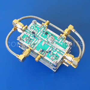
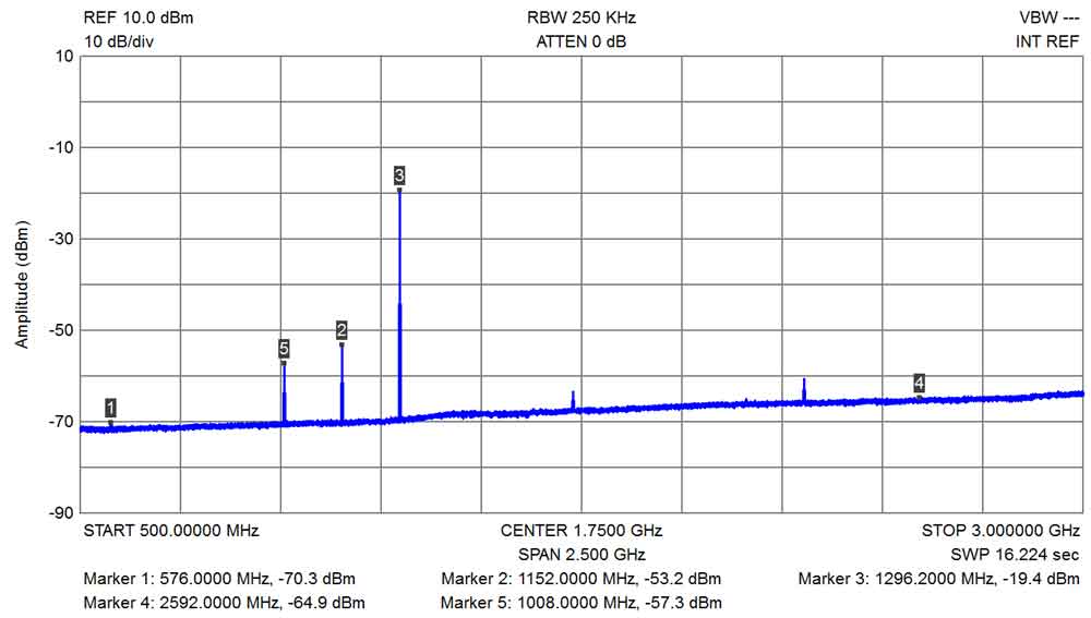
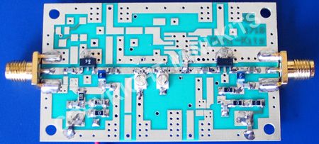
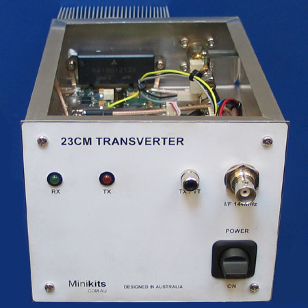
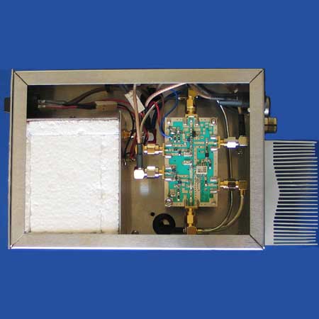
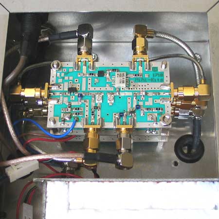
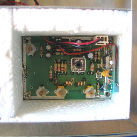
A complete 23cm Transverter can be easily constructed using a number of Kits and Components available from Mini-Kits. The picture above shows the basic prototype Transverter for 1200MHz using Mini-Kits designed tune able filters. The design consists of three PC board Kits, a 1152MHz oscillator multiplier EME1152-MLT KIT, 1180-1700MHz converter EME1.2G-CV17,and 1200MHz TX driver amplifier EME1.2G-AMP1 KIT. The standard I/F frequency is 144MHz, but frequencies between 100 and 150MHz could be used as long as they are not harmonically related, or when mixed produce spurious output on the 1200MHz 23cm band.
The 23cm Transverter uses modern low noise high gain amplifiers, including the Mini-Circuits Gali, and Avago MGA series, which makes it very easy to construct a high performance Transverter with fewer devices. The receive converter uses a low noise MGA-86563 GaAs MMIC, guaranteeing better than 2dB noise figure, and a high IP3 MGA31389 second receive amplifier and +17dBm mixer is used for good strong signal handling. The transmit converter uses the same +17dBm mixer which allows a higher input on 144MHz, for more RF output on the 23cm band producing a cleaner transmit signal. All three boards have on board regulators, that allow a minimum voltage of +10vdc for portable operation on a +12 volt battery.
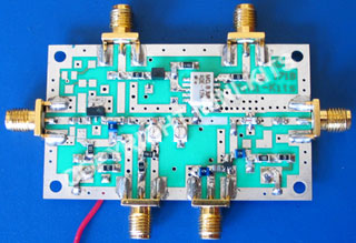
The EME1.2G-CV17 is a transmit up, and a receive down converter, with a frequency tuneable between 1180 and 1700MHz. The low frequency range is limited by the 1150MHz high pass filter in the receive converter, and the ADE-17H mixer's maximum frequency of 1700MHz. The converter is ideal to use for the 1240 to 1300MHz band to construct a complete 23cm Transverter using a 144MHz I/F.
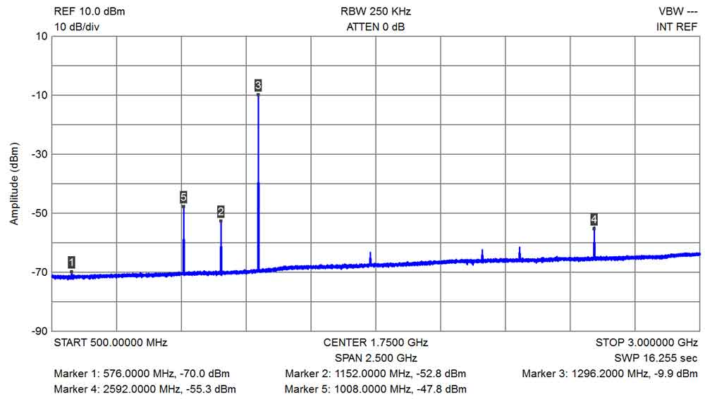
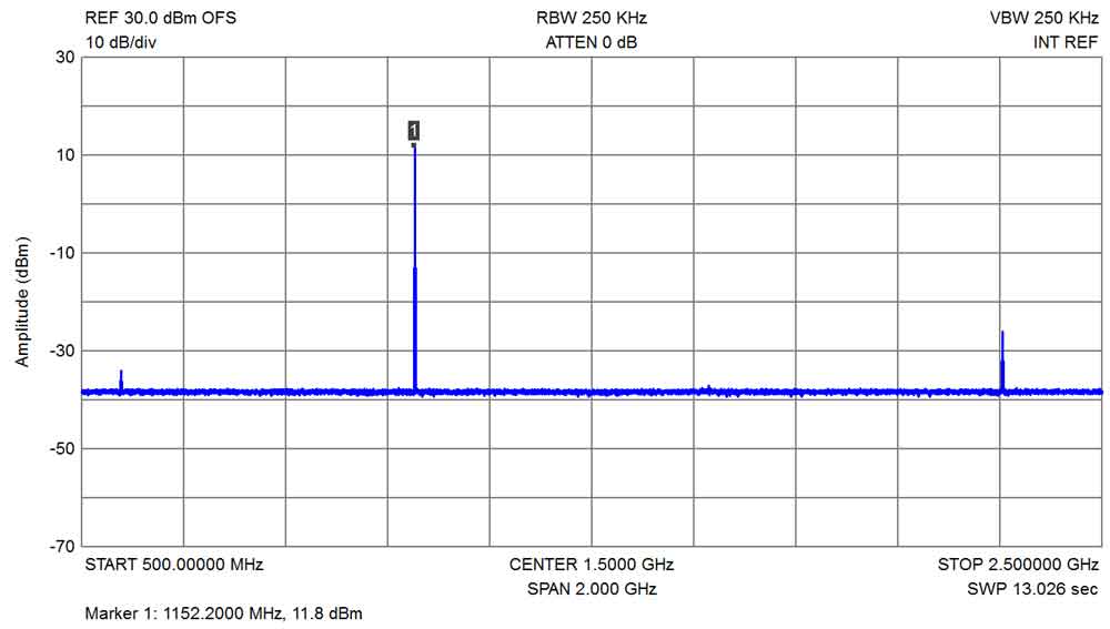
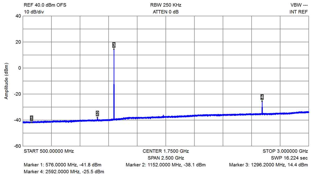
The 1152MHz multiplier is constructed on a EME171B Universal
Microwave board, and has been specifically designed as a local
oscillator multiplier for 1200MHz Transverters, RX converters, or as
a multiplier for ATV. A Mini-Kits designed 2 section filter is used
to effectively filter out harmonics and oscillator noise allowing
Transverter I/F frequencies down to 144MHz to be used.
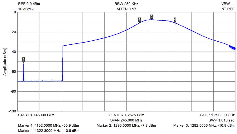
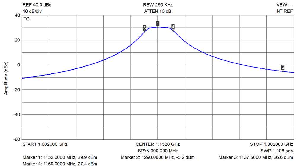
The tuneable filter allows the Kit it to be used on frequencies from
approximately 960MHz to 2GHz. The filter bandwidth is less than
35MHz at 3dB and less than 90MHz at 20dB. The tuning of the filter
can be quite easily done using just a simple RF diode probe on the
output, and tuning for maximum DC volts on a multimeter.
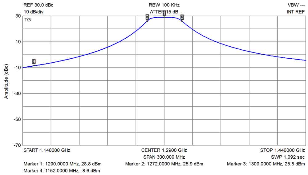
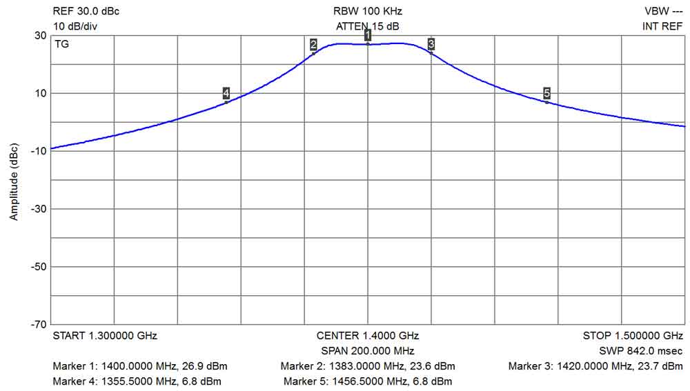
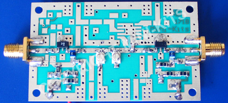
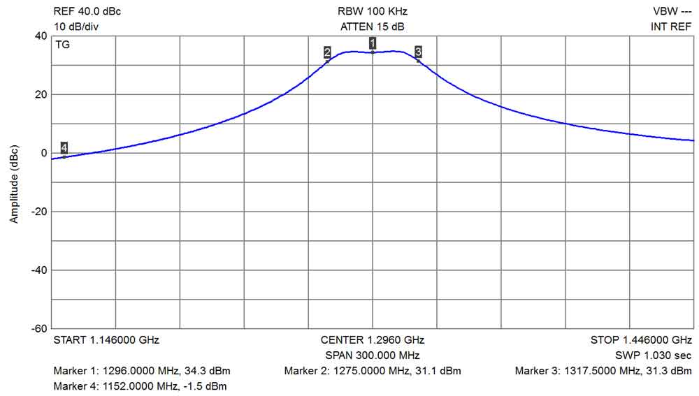
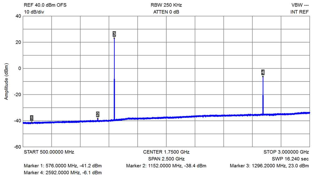
The EME1.2G-AMP1 is a high gain transmit driver amplifier designed for the Mini-Kits 23cm Transverter. The amplifier has up to 34dB gain, and an output 1dB compression of +24dBm. The amplifier uses a two section filter that has a wide tuneable frequency range of 960 to 2000MHz, and provides excellent filtering for a very clean output.
A number of Kits and Components are required to construct a complete Transverter. The 23cm Transverter Block Diagram outlines the Kits required to construct a complete Transverter.
For the 576MHz Local Oscillator, the EM175 Kit can be used. The EME177 Heater Kit is high recommended when used with the 60 degree C Crystals from Mini-Kits For more information on the EME175 oscillator, and EME177 Heater Kits please see the EME175 Kit web page.
For sequencing and switching of the RF and power supply voltages the EME166 Sequencer Kit is highly recommended.
For Antenna switching, the EME225 HF3-53 Relay Kit is ideal, and will handle at least 20Watts of RF at 1200MHz.
For a Power Amplifier the Mitsubishi RA18H1213G Kit can be used that will produce up to 18Watts output on 1200MHz.
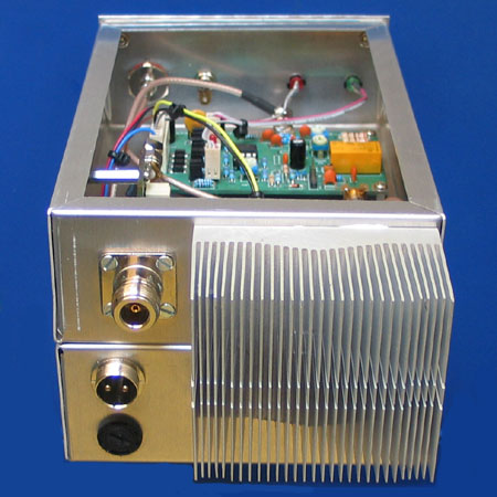
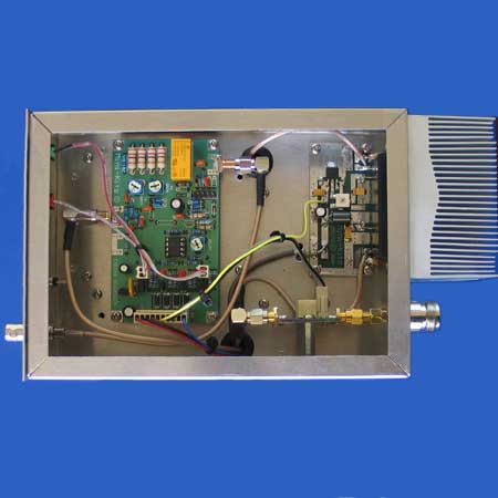
The prototype Transverter below uses 2 x Hammond 1444-12 Aluminium Chassis enclosures ( 178x127x51mm ) which were bolted together. The construction is very time consuming due to the small size of the enclosures, and larger enclosures are recommended for inexperienced constructors. The front panel was cut from 1mm Aluminium sheet, and a white plastic Avery label was printed on a laser printer and stuck onto the panel. The heat sink is a P4 Pentium which was surplus from an old PC. The heat sink however should have a fan if the Transverter is to be operated on modes like FM.
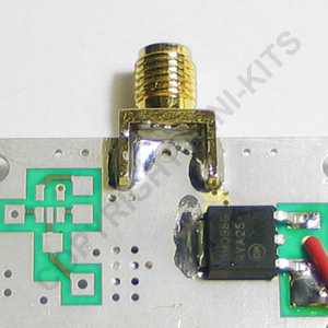
Mounting the PA module at right angles to the PA board is not recommended as the RF grounding between the rear of the module and the PC board is critical on 1200MHz. Some initial problems with oscillation from the PA module were found due to the large distance between the outer of the coaxial cable where it terminates, and the actual modules RF ground. Re routing the coaxial cables to various positions in the enclosure fixed the problem but a spectrum analyzer is required to test for the oscillation. It is highly recommended that the PA module and PC board are mounted flat inside a RF tight enclosure, and bolted to a heat sink.
1/ Low receive gain, check that the ground connections on the sides of HFCN-1200 filter are soldered to the board.
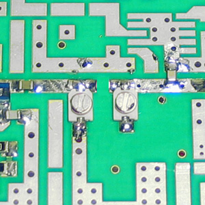
2/ Cannot peak the 1200MHz filter trimmer capacitors on receive for an increase of noise on a 144MHz SSB receiver. This can be many things like no 1152MHz LO drive, or as found on a customers board, one of the ends of the trimmer capacitors was not soldered to the stripline.
3/ Erratic or difficult tuning of the 1200MHz filter can be damaged trimmers by either getting too much solder flux inside them, or by wearing the trimmers out by tweeking them too many times.
1/ Cannot peak the 1152MHz filter trimmer capacitors for an output from the multiplier. Check that the ends of the trimmer capacitors are correctly soldered to the striplines.
1/ There are currently no issues with this Kit.

