EME222 SDR Recever Antenna Switch
- EME222 SDR RX Switch Description:
Updated! April 2023
- EME222 Application Block:
- Kit Constructors Alert:
- EME222 Kit Construction Notes:
- EME222 Kit Performance Tests:
- Kit changes and Updates:
Updated! Feb 2024
- Buy a EME222 Kit:
NEW!
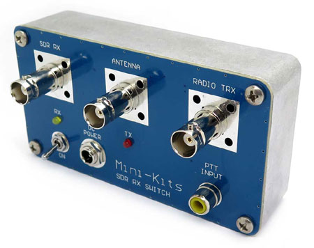
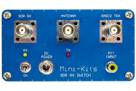
The Software Defined Radio, ( SDR ) RX Switch has been designed to allow an SDR or additional Receiver to be used in conjunction with a HF Radio Transceiver on a single Antenna. The switch provides >70dB isolation protection to the SDR RX when RF is applied to the Radio TRX connection from a 100 Watt HF to 6m Transceiver. In receive mode, a two way RF splitter is used to split the incoming Antenna signals between the SDR RX, and Radio TRX connectors. The switch is ideal if you want to use a SDR Play or similar SDR receiver for a spectrum scope on the same Antenna as a HF Transceiver. The switch has a hard wired PTT input that suits most Transceivers, and also an RF detector circuit for further protection incase the hard wired PTT is not connected. When the switch is powered off, the SDR RX connection is terminated into 50ohms, and the Antenna is connected to the Radio TRX connection through the Relays.
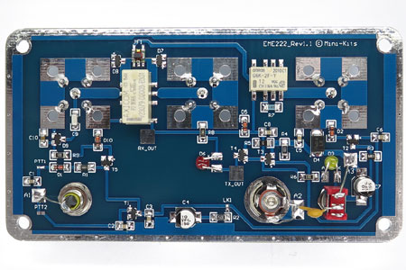
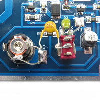
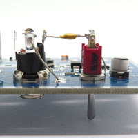
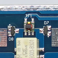
The images below show both sides of the board. The construction is quite easy if you start with the SMD components on the bottom side of the board first, and then fit the conventional leaded components and connectors after. The only difficult part is the correct orientation of the 2 way splitter. There is a small resistor on the top of the component that should line up with the squiggly line of the board overlay. Click the pictures below for a more detailed view.
All EME222 Rev Kits are specified for use from 500kHz to 150MHz. They are not suitable for use on the 70cm band due to Relay isolation and unacceptable return loss due to Relay capacitance. The design would need changing to a high frequency RF relay which would require redesigning the PCB. However the on board RF detector circuit is only suitable from HF to 54MHz with 100W due to the value of C9 22pF which is too large for the 2m band. Using 100W on the 2m band could cause damage to the RF detector due to C9 passing too much RF to the detector circuit. A 2m / 70cm version is currently being designed.
1/ Rev1.0 Kits, To improve inter-modulation, D7 and D8 have been changed to SMP1330-005LF PIN Limiter Diodes in the Rev1.1 Kits.

