EME208 9MHz Transmit Modulator Kit
- EME208 Module Description:
Updated! June 2022
- M1 Transceiver Block
Diagram Rev1.5:
Updated! Apr 2017 - Kit Constructors Alert:
Updated! Feb 2015 - EME208 Kit Construction Notes:
- EME208 Kit Performance Tests:
- Kit changes and Updates:
Updated! Aug 2021 - M1 Series Transceiver Webpage:
- Buy a EME208 TX Modulator Kit:
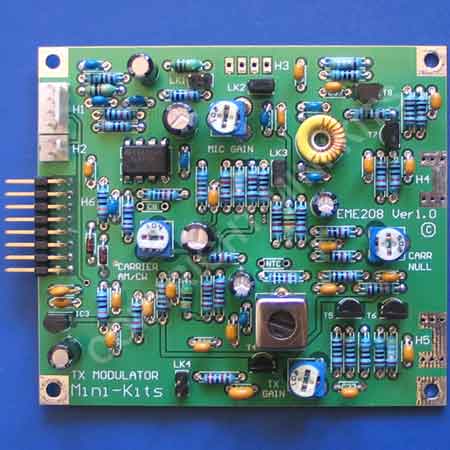
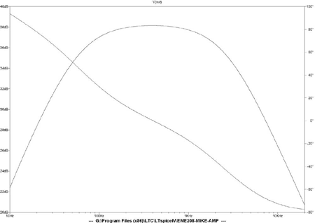
The Mini-Kits EME208 is a Transmit Modulator module that has been designed around the MC1496 balanced modulator IC, and can generate amplitude modulation ( AM) , double sideband ( DSB ), an continuous wave ( CW ) modes. The design is optimized for use with a 9MHz beat frequency oscillator ( BFO ), but can also be used with an IF up to 10.7MHz by re tuning. It is recommended that the M1 series EME205 BFO Demodulator be used as it has been designed to be used with the EME208 transmit modulator. The modulator features a quality microphone amplifier that is suitable for low impedance 500ohm to high impedance microphones and has the option to plug in an optional speech processor module that will be available at a later time. RF output from the modulator is up to 0dBm output
The module is controlled through a single 16 Pin IDC header connector, making it easier to interface to logic circuitry. See the M1 Transceiver Block diagram for the connections to this module.
The EME208 is a part of the M1 series building blocks to construct a high performance M1 HF Transceiver. The M1 HF Series Kits have been designed to allow easy construction due to the use of mainly leaded components for those that don't like surface mount devices. Modern SMD components are only used when required due to availability of components, or for better performance. The RF modules are all designed with a 50ohm impedance making it easy to interconnect with the other M1 series modules, and your own homebrew circuit designs.
1/ There has been a modification to the +8V/TXA where it supplies the TL071 microphone amplifier. The track that connects connector H6 pin 4 to the junction of R4 and C6 needs to be cut and a 1N4148 diode placed in series. This then allows the +8V/TXA voltage to switch much faster back to 0 volts without C5 100uF capacitor slowing the voltage from discharging. This may be part of the solution to the intermittent failure of the GALI-84 driver and BAR64-05 diode on the EME210 power amplifier module. The modification details can be downloded here.
1/ August 2021, R17 has been changed to a 120K to better set the AM modulation for less distortion.
2/ There has been a modification to the +8V/TXA where it supplies the TL071 microphone amplifier. The track that connects connector H6 pin 4 to the junction of R4 and C6 needs to be cut and a 1N4148 diode placed in series. This then allows the +8V/TXA voltage to switch much faster back to 0 volts without C5 100uF capacitor slowing the voltage from discharging. This may be part of the solution to the intermittent failure of the GALI-84 driver and BAR64-05 diode on the EME210 power amplifier module. The modification details can be downloded here.


