EME171 Series Kits
- EME171 PC board Description:
Updated! June 2022! - Supported Devices: Lineup:
- EME1152-MLT Frequency Multiplier Kit Notes:
- EME1152-MLT Performance Tests:
- EME1.2G-AMP1 Driver Amplifier Kit Notes:
- EME1.2G-AMP1 Performance Tests
- EME2256-MLT Frequency Multiplier Kit Notes:
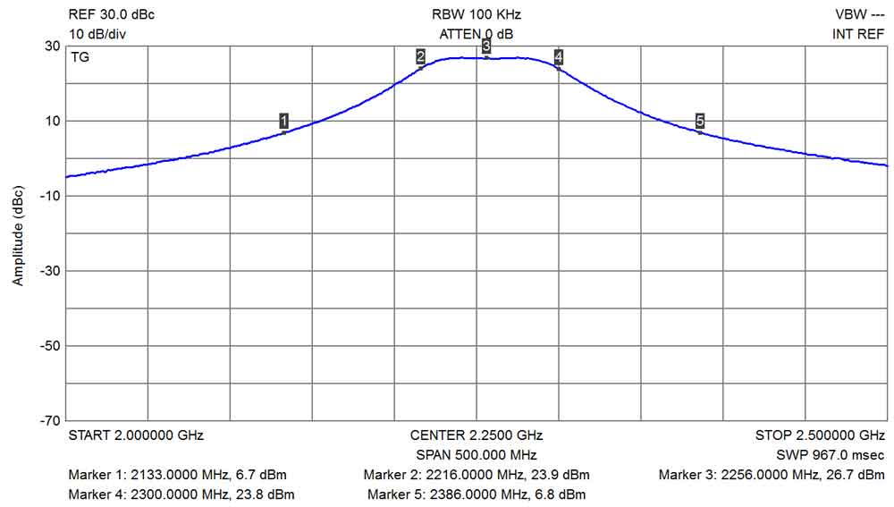
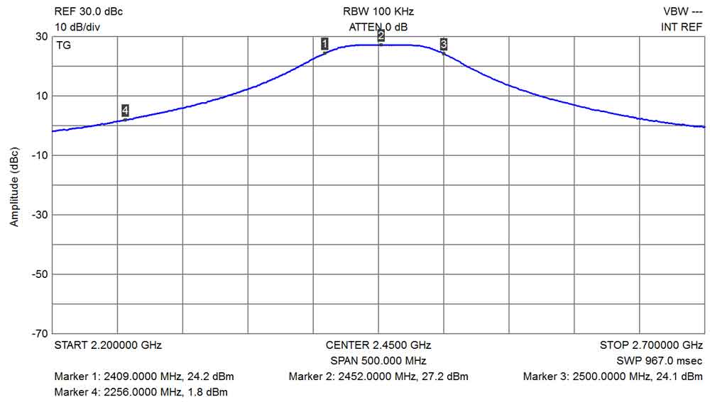
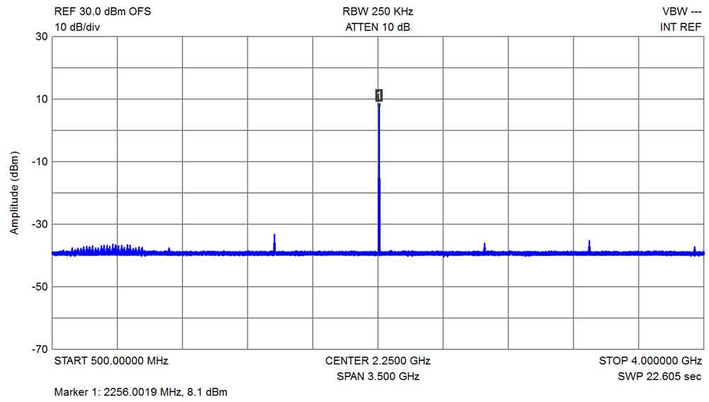
- EME2256-MLT Performance Tests:
- Changes and Updates:
- Buy the New EME200 PC Board:
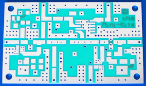
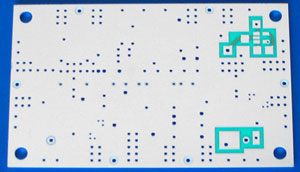
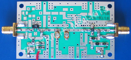
The EME171B Universal Microwave PC board was designed as a low cost way of experimenting on the microwave bands, and allows the fitting of two RF amplifier devices, a single pipe-cap cavity filter, and RF mixer. The board can also be used to construct local oscillator multipliers, low noise amplifiers, RX/TX converters, & RF driver amplifiers. The new revision B board allows for the fitting of a TPS60400 -ve bias generator for a GasFET or HEMT, and onboard regulator in a D Pak.
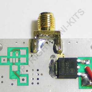
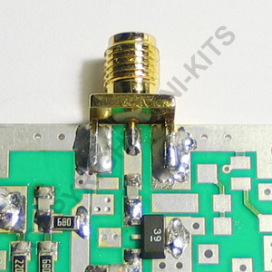
The board was designed to support a number of commonly available RF devices in either the SOT-89 or X-Pack style packages, including the Avago MGA86563 in a SOT-363 package. Support of other SOT-363 packaged devices like the MGA85563 can be used if they are rotated 90 degrees due to the different pinout. Commonly available devices including the Mini-Circuits, MAR, ERA, Gali, and Avago MSA series monolithic amplifiers can be used, along with the Avago MGA86576 X-pack.
Designing a 5.7GHz Transverter to have enough gain and a low noise figure on receive is not trivial. We require around 25dB total gain from the antenna input to the IF output with a Transverter which when adding the losses of filters and mixers, a total amplifier gain of around 38dB is required. There are very few devices that have high gain at 5.7GHz let alone 10GHz, which makes it marginal to get enough gain out of two devices on the one board without adding another EME171 board with the extra gain of another amplifier device. It is suggested to use the MGA86563 at 5.7GHz, ( 13.7dB gain 2dB NF ) for the first RF amplifier, followed by a MGA30989 ( 8.4dB gain 2dB NF ) on one board, and a GALI-39 ( 17dB gain 2.8dB NF ) and a MCA1-85 mixer on second PC board.
For 10GHz a second EME171 board with a MGA86576 or external low noise amplifier will need to be added to get enough gain on receive.
- AMPLIFIERS: Mini-Circuits, MAR, ERA, Gali, PGA, PHA, Avago, MSA, MGA86563, MGA86576, MGA85563, NEC NE3210S01, NE3512S02,
- MIXERS: Mini-Circuits, MCA series, MCA1-24+, MCA1-60+, MCA1-85+, MCA1-12G+, ADE2 / 5 / 11x / 30
- FILTERS: Pipecap 1/2" to 1 1/8", Mini-Circuits HFCN, LFCN
- COMPONENTS: Capacitors, Resistors 0603, 0805, 1206,
- Inductors, 0805, 1008, 1206, 1210
- OTHER: 78M Series Regulators D Pak, TPS60400 -Ve voltage Gen
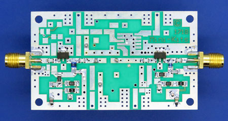
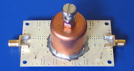
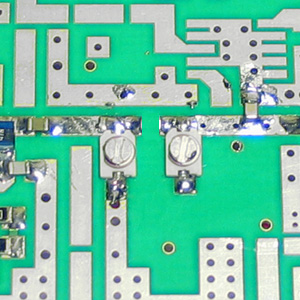
The pictures below show the EME3400-MLT Kit that uses a 7/8" pipe cap and 2x GALI-39 devices. The board allows the fitting of pipe caps up to 1 1/8", and various other filters like the Mini-Circuits LFCN/HFCN, and Mini-Kits designed 2 section tunable filter
The 2256MHz multiplier is constructed on a EME171B Universal Microwave board, & has been specifically designed as a local oscillator multiplier for 2400MHz transverters, RX converters, or as a multiplier for ATV. A Mini-Kits designed 2 section filter is used to effectively filter out harmonics & oscillator noise allowing Transverter I/F frequencies down to 144MHz to be used.
The tuneable filter allows the Kit it to be used on frequencies from approximately 1.8 to 2.6GHz. The filter bandwidth is less than 90MHz at 3dB and less than 260MHz at 20dB. The tuning of the filter can be quite easily done using just a simple RF diode probe on the output, and tuning for maximum DC volts on a multimeter. BUY THIS PRODUCT
1/ The PC board was modified in late 2012 to better suit devices for the higher 3.4 to 10GHz microwave bands. Some device pads were moved closer to the PC board edge for lower NF on receive. The board was also modified to allow the fitting of a -ve bias generator TPS60400 so that a GasFET or HEMT could be used on either 5 or 10GHz if required. Pads were also added on the bottom of the board so that a 78M series voltage regulator could be fitted.

