EME166 Transverter Sequencer
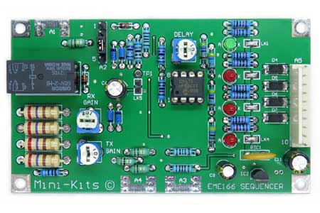
The EME166 Sequencer replaces the very popular EME66 Kit that has been produced for well over 10 years. The updated Kit makes connection to other circuitry much easier due to a single 10 way header connector on the board. The Sequencer can be used to control Transverters with various component like antenna relays, power amplifier, or receive preamplifiers. It is also suitable for sequencing the switching of high power RF amplifiers with a transceiver. The circuitry incorporates both DC and RF sensed inputs that can be used to control the switching of the sequencer from RX to TX mode. The sequencer suits Transverters with either a single, or dual I/F connections. The circuitry uses a PIC micro controller and MosFET switches, and has over voltage and current protection. The 23cm Transverter Block Diagram shows how this Kit can be used.
- I/F TX Input: 28MHz to 500MHz up to 4 Watts maximum
- TX / RX Delay: Adjustable trim pot
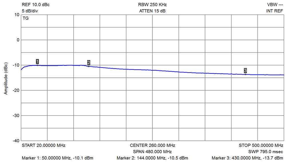
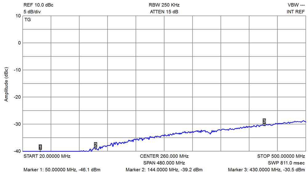
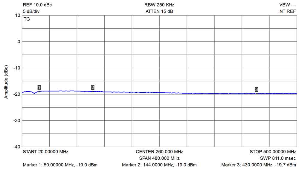
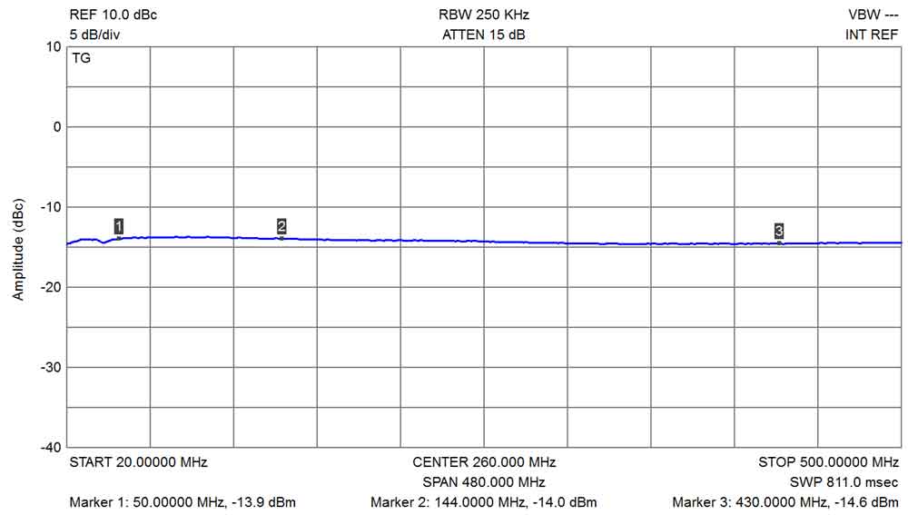
- TX Attenuation: Adjustable trim pot -14 to -39dB @ 144MHz
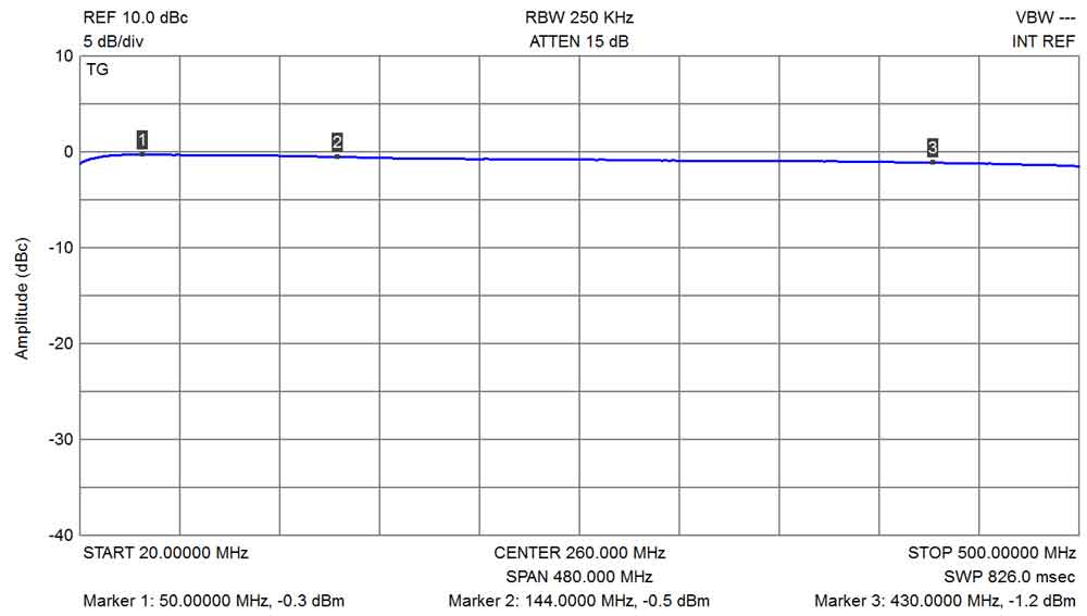
- RX Attenuation: Adjustable trim pot -0.5 to -10.5dB @ 144MHz
- Switched Inputs: ( PTT ) +12vdc ( FT290R ), 0vdc to TX ( IC202 ), RF sensed switching also onboard
- Switched Outputs: Delay1, RX +12v, all TX outputs 0v ( RX Power
)
Delay2, RX 0v, TX +12vdc ( coaxial antenna relay )
Delay3, RX 0v, TX +12v ( power supply to TX power amplifier )
Delay4, RX 0v, TX +12v ( TX stages power supply ) - Power: +8 to +14vdc supply. Current RX mode 35mA, TX mode 90mA ( includes onboard relay )
- PC Board Size: 94 x 55mm
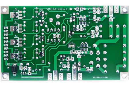
1/ The PC board had minor changes to update it in July 2014. The circuit is exactly the same and no changes were made to the component values.
2/ A modification to allow easy switching of Linear Amplifiers that require a grounded input can be found here. The BC847 will easily switch the input of most amplifiers as only low current is required.
3/ There has been a report of the onboard relay not deactivating in RX mode. The fault was traced to the 2N7002 that drives the relay that was found to have leakage from the drain to gate. The 2N7002 was replaced and this fixed the fault.
4/ Rev2.x Kits There has been a report of failure of one of the NDT2955 MosFETs due to shorting out the RX power to ground. Please let me know if you have had any issues with MosFET failures as the PTC and high current capability of the MosFETs should protect them from damage.
4/ Rev3.x Update July 2019. Changed the NDT2955 Fets to DMP3099L.

