EME165 Ver1 AD995x DDS Kit
- EME165 Kit Description:
UPDATED! June 2022
- M1 DDS Controller Block
Diagram:
- EME165 Kit Construction Notes:
- EME165 Performance Tests:
- Kit changes and Updates:
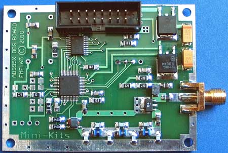
The Mini-Kits EME165 Version 1 Direct Digital Synthesizer Kit has been replaced with the ( Revision 2 ) R2 and can be used with either the Analogue Devices 14 bit 400MHz AD9951, or AD9954 DDS chip, and is idea as a signal generator or VFO for a receiver project. The AD9954 has the internal high speed comparator and extra functionality which may not be needed for many applications. The 14 bit A-D produces much lower spurs compared to the 10 bit AD9850/51 chips that can have some very high -30dBm spurs on some frequencies, so is more ideal for use as a VFO for a receiver.
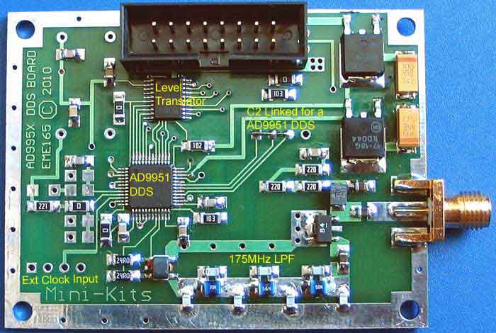
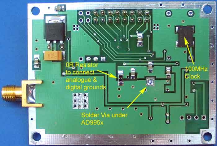
An on board 100MHz 5ppm oscillator uses the x4 DDS multiplier to produce a maximum recommended output frequency of 160MHz. The DDS output uses a 175MHz 7th order elliptic Low Pass Filter, which is used to reduce the aliases and quantization noise from the DAC outputs.
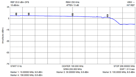
The 3dB RF Bandwidth of the DDS output is around 60kHz to 145MHz, and is mainly limited by the low frequency 1:1 Transformer on the DDS DAC outputs along with the coupling capacitors. The Transformer has the benefit of reducing even order harmonics, and produces +3dBm more output power. A high 25dB gain Gali amplifier with an IP3 of +38dBm was chosen as it was able to produce a very clean RF output when under driven. The DAC current RSET was then able to be adjusted to provide a very good Spurious Free Dynamic Range, and drives the high gain Gali device to around 1/2 its capable output power to produce a clean +10dBm output.
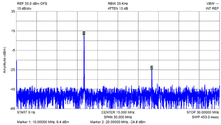
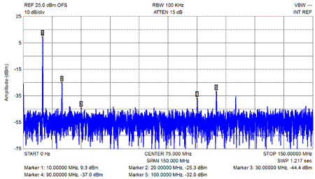
With reference to the fundamental output @ 0dBm, the 100MHz clock is -45dBc, 2nd Harmonic -36dBc, 3rd -54dBc, all other spurs are less than -50dBc.
The board is compatible to connect 5v logic from a micro controller as it uses a bidirectional translator chip to interface the 5v on the main IDC header connector to 3v to suit the DDS logic. The various connections on the header allows the board to be used with many micro controller projects found on the WEB, including the Mini-Kits M1 DDS Controller Kit using the M1-DDS software.
A number of resistors, R1, R2, and R3 are used on the board as links that may not be required for your application, but are required when using the M1-DDS Controller and M1-DDS software. See the Kit schematic and board overlay diagrams for where the resistors are located.
The picture below shows how all the C2 connections are grounded using a wire link when the board is used with a AD9951 chip.
1/ Kits after April 2016. The 100MHz CMOS clock has been changed to a Fox brand HC73 as they are much low phase noise compared to the MEMS oscillators that have been previously supplied with Kits.
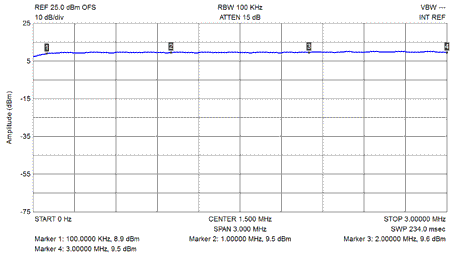
2/ Kits were updated from mid March 2012 to improve the low frequency response down to 100kHz. The 3x 0.1uF and 10uH on the Gali-84 amplifier have been replaced with 3x 1uF and 100uH. A link here shows the results of test done by Keith Williams. Download
3/ In 2014 the TC1-1T transformer was replaced with a Macom ETC1-1T-2TR which has a slightly better low frequency response.
4/ A problem occurred when the HF-DDS software when first powered up could not recognise the AD995x chip. The fault was traced to a faulty TXB0108P level converter chip on the EME165 DDS board.
5/ No RF output from the DDS board. Check with a sensitive receiver tuned to the DDS output frequency to see if it is actually outputting RF. If it appears to be working and that the RF output is just low go to 3 below. Check that the 100MHz oscillator module is working. Most problems can be due to bad solder joints on the AD995x and TXB108P chips. Recheck that all pins on the these chips are soldered to the tracks on the board, and that there are no bridges between pins. A good magnifying glass and light is required to clearly see the connections. Sometimes pressing down on the AD995x chip can make the DDS work. If you have developed your own software refer to 4 below.
6/ Low RF output from the DDS Board. There are a number of things that can cause this. The most common is, bad solder joints on the I and Q output pins of the AD995x DDS, or one of the chip capacitors in the RF path being cracked. Other things that can cause this is, the 10uH choke not being soldered to the board, or one of the Gali-84 leads being shorted to ground, which turned out to be a solder bridge under the Gal-84 pins. One recent Kit had a dry joint on one of the pins of the T1-1T transformer that connected to the 24ohm resistor.
7/ Using the EME165 DDS board with your own software. Please make sure that you are using the links on the board correctly to suit your software. This has been a common problem experienced by a number of constructors that have written their own software and could not make the board work. The reset line to the AD995x chip will need to be pulled low in software from the micro controller to reset to DDS. Mini-Kits is not able to supply software support on how to write your software to talk to the AD995x.
8/ If you need to drive the DDS board with a 3.3v micro controller, then the 5v supply to pin 19 can be disconnected by cutting the track on the bottom of the board where it goes to pin1 of the C1 header connector. Then connect a wire from the LD1117D T33C 3.3v regulator with a wire to the 0.1uF capacitor under the TXB0108 that connects through the board to pin 19 of the TXB0108.
9/ RF Output not clean with spurious and main output not on the correct frequency. Check the 100MHz clock module to make sure that it is working.

