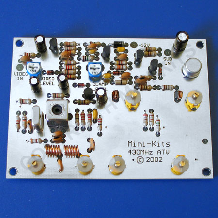
EME44 430MHz Video Transmitter
- EME44B Kit Description:
Updated! June 2022 - Download the complete Kit Notes:
- Kit changes and Updates:
The EME44 is an Amplitude Modulated Double Sideband Television transmitter for the 70cm Amateur band. The design uses a sync stretcher and high level modulation to overcome the linearity requirements when transmitting Television signals, and produces up to 100mW, ( +20dBm ) output. The transmitter will require a Filter on the output to reduce the Double sideband AM Bandwidth. Tuning this filter to the USB of the AM signal will reduce interference to other users of the 70cm band, along with increasing the efficiency of the Power Amplifier. A Helical filter or a suitable interdigital filter, will be required for transmitting on 444.250MHz in all parts of Australia as per the current regulations to reduce the lower sideband. Please check the local Radio regulations before purchasing.
1/ I have received information from one constructor that he was unable to make his transmitter stable and it would not produce a correct picture on a TV monitor. He had tried tuning it for many hours and I expect that many others have had the same problem. The Toko coil supplied, coil L1 should be a 0.13uH not 0.1uH and should be marked 100 114 on the can. The 0.13uH coil along with the parallel 33pF capacitor is resonant close to the 71 to 74MHz crystal frequency. The incorrect 0.1uH coil makes it resonant somewhat higher in frequency, so it cannot be tuned down to the 70MHz region. See the notes eme65doc by Kevin ZL1UCG Kit on how to determine what frequency the coil/capacitor combination is resonant. The coil may be able to be modified by removing the can and adding an extra turn to the coil, but this could be difficult for some constructors. Please email us if you have the problem and we will post a replacement coil to you.
2/ Many problems associated with this Kit are due to poor soldering or the chip capacitors not being soldered or they may have been cracked when fitted. Problems also exist with the two coils L2 and L3 not being wound correctly with the correct number of turns and spaced above the board by 2.5mm. The coils are rather critical, and if they have a turn less or more, then the two trimmer capacitors C1 and C2 associated with the tuning of the coils will not peak at the 3rd harmonic, ( 213/222MHz ) of the crystal. Refer to the Images above on how the coils should look.
3/ There have been reports of spurious signals from the output depending on the tuning of the L1 and the trimmer capacitors. First check to make sure that the crystals case is grounded to the board by soldering some wire from the crystal case to the top of the board. The other symptom of the crook crystal was nearly a 5dBm loss of output power from the transmitter. If the crystal is good then L1 should be able to be tuned in either direction and only the output power will drop, but the frequency will remain locked to the crystals frequency. Also check that the 1nF chip capacitor on the first BFR92A is soldered and not cracked. If you have not checked if you have the correct Toko coil fitted then refer to section 1 above first.
4/ Any problems with burning up of either of the 10ohm resistors could be due to a shorted trimmer capacitor C3 or C5 on the associated tuned circuit. Check the trimmer with a multimeter for intermittent shorts by adjusting it.
5/ If you have low output power and trimmer capacitor C3 or C5 won't tune, then a common problem is one of the two 220pF chip capacitors that are soldered on the bottom of the board, many not be soldered on one end, or one is cracked.
6/ Tests by Kevin ZL1UCG on the Capacitor and Coil combination used in the Butler Oscillator. eme65doc The chart has recommendations for the capacitor that should be used to resonate the tuned circuit correctly.

