EME215 RX Active Switch
- EME215 RX Active Switch
Description:
Updated! June 2022 - EME215 Application Block:
- Kit Constructors Alert:
Updated! Dec 2019 - EME215 Kit Construction Notes:
- EME215 Kit Performance Tests:
- Kit changes and Updates:
Updated! Feb 2022 - Buy a EME215 Kit:
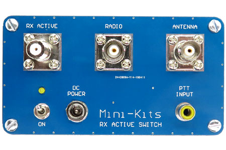
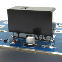
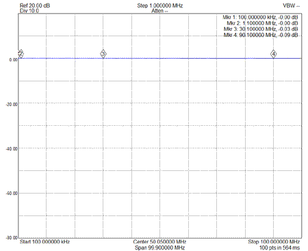
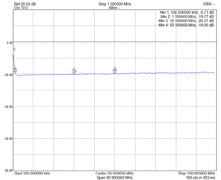
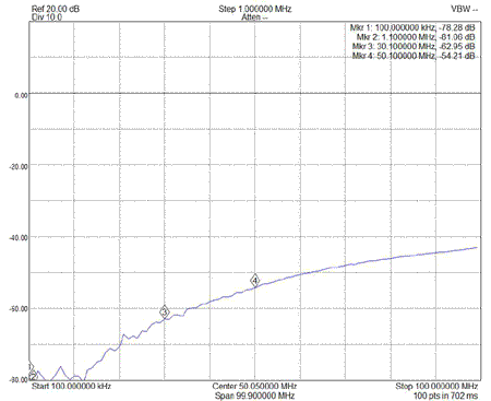
The RX Active Switch has been designed for HF Radio Transceivers that only have a single antenna socket and no optional RX only antenna input. This allows a separate Loop or Active whip receive antenna to be connected in RX mode, and a main Transmit antenna to be connected in TX mode. The design incorporates a Bias Tee ( DC power injector ), so that active whip and loop antennas can be directly powered via the coaxial cable. A Relay and RF detector circuitry is used to disconnect the RX Active antenna to protect it when DC power is disconnected, or when in transmit mode. The active switch has better than 50dB isolation up to 50MHz, so can easily handle up to 500Watts of RF power.
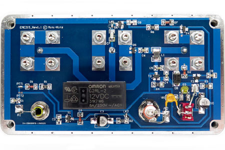
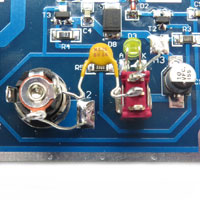
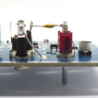
The images below show both sides of the board. The construction is quite easy if you start with the SMD components on the bottom side of the board first, and then fit the conventional leaded components after. The only difficult part is the winding of transformer TFMR1 as the windings have to be correctly connected for the correct phasing polarity. An incorrectly phased transformer cancels the signals and produces no gain. Click the pictures below for a more detailed view.
1/ Kits from Rev1.2 To improve intermodulation, D5 has been changed to a SMP1330-005LF PIN Limiter Diode.
2/ Kits before April 20, 2021 were supplied with a FDN338P MosFET. The MosFET seems a bit marginal with respect to the Vgs only being +/-8v. It is suggested that if it fails then it can be replaced with a higher Vgs MosFET like the DMP3099L-13. Kits supplied after April 20 2021 are now supplied with the DMP3099L-13 MosFET.
3/ The board overlay diagram in Kit notes Rev1.0 shows D7 around the wrong way. The anode connection should be to ground.
4/ A report of the LED not fully turning off when going to TX mode was traced to the FDN338P MosFET being leaky. This has been reported a couple times and could be due to component reliability, but possibly due to high RF levels when first going into TX mode, and using the RF sensing circuit and not the PTT input for switching.

