EME182 HF Active Antenna
- EME182 Active Module Description:
Updated! June 2022 - Kit Constructors Alert:
- EME182 Kit Construction Notes:
- EME182 Alignment:
- EME182 Kit Performance Tests:
- Antenna and Enclosure Mounting:
- Kit changes and Updates:
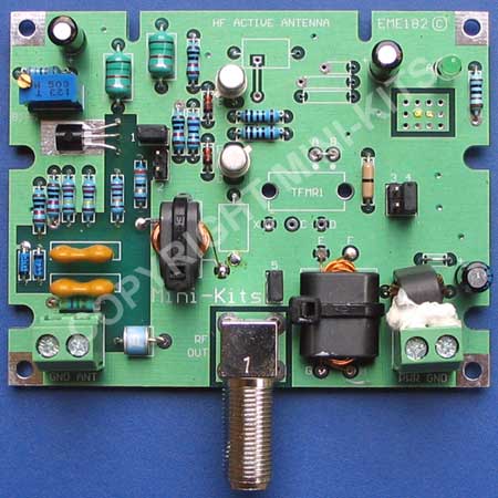
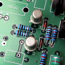
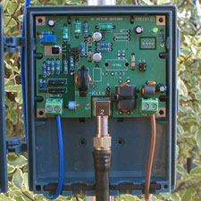
The HF Active Antenna has been designed to be easy to install, and covers a wide frequency range from 100kHz to 80MHz. It is particularly useful for those that have antenna restrictions or limited space to install a full size antenna, and can be used in antenna arrays for noise cancellation or beam forming. The design incorporates static and lightning protection, and has a broadband 50ohm output impedance suitable for driving most receivers. A J310 FET is used as the active device, and along with a complementary push pull output buffer produces high output second and third order figures reducing the possibility of inter modulation on the received signals. The design incorporates power supply decoupling so that power can be fed to the Active circuit via the coaxial cable.
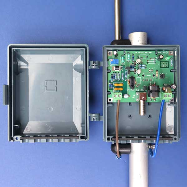
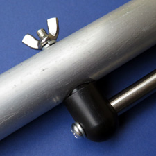
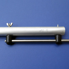
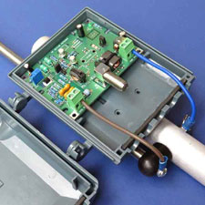
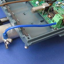
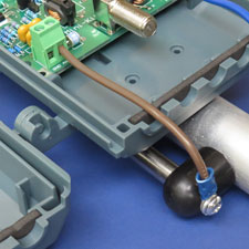
The recommended Antenna is a 1.9 metre long telescopic stainless steel side mount truck antenna. It is physically short as an antenna for the low frequency HF bands, and will appear as a small 22pF capacitor to ground on the active input circuit. Antennas longer than around 2.5 metres, may increase the possibility of strong signals overloading the active circuit causing inter modulation. The antenna is ideal for mounting directly onto a 2 metre long 1 inch 25.4mm diameter square or round aluminium tube. The active circuit can then be easily mounted onto the same tube, and then short connection wires are connected from the antenna to the active circuit. At least 3 ground radials 3 metres long each are laid along the ground for the best performance.
Testing indicated that receive signals below 10MHz may require an 10dB gain amplifier on the receiver input to increase signals to a more comfortable level due to the short antenna length. Some modern receivers incorporate preamplifiers that can simply be switched on, on the lower bands.
In very strong AM broadcast areas, some lower quality receivers without good filtering may suffer from inter modulation from strong signal overload. A suitable 1.8MHz high pass filter should be fitted at the receiver input to reduce broadcast band signal levels.
1/ The AP90 Aeropro Pillar mount antennas have been discontinued by the manufacturer. Its is suggested that the Aeropro AP120 is used to replace the AP90 as an antenna of around 1 metre long is only required and antennas that are longer offer no performance increase.
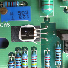
2/ There has been a problem with not being able to adjust the 50k trim pot for the correct current for the J310 Fet. This equated to around 30mA which is around 1.17 volt across the 39ohm source resistor on prototypes. There may be some variation with the J310 FETs that cause the current setting for best IP3 to be lower than 30mA. So the source resistor may need changing to a higher value around 100ohms to set the current for some FETs. Aim for around 25 to 30mA by measuring the voltage across the source resistor for best IP3.
1/ There has been a problem with not being able to adjust the 50k trim pot for the correct current for the J310 Fet. This equated to around 30mA which is around 1.17 volt across the 39ohm source resistor on prototypes. There may be some variation with the J310 FETs that cause the current setting for best IP3 to be lower than 30mA. So the source resistor may need changing to a higher value around 100ohms to set the current for some FETs. Aim for around 25 to 30mA by measuring the voltage across the source resistor for best IP3.
2/ Low 12vdc to the Active circuit when fed with a bias tee through coaxial cable. Check the bias tee to make sure that it is capable of supplying at least 100mA @ 12vdc. This can be done by placing a load resistor on the 12vdc output of the bias tee. If the test fails then replace the PTC inside the bias tee.
3/ The AP90 Aeropro Pillar mount antennas have been discontinued by the manufacturer Aeropro. Its is suggested that the 3 section 120cm long Aeropro AP120 is used to replace the AP90. Antennas over 1 metre are not really going to produce stronger signals, and whips over 2 metres in length could actually degrade the performance due to overload.

