EME181 Series Bias Tee Kits
- EME181 Description:
Updated June 2022 - Kit Constructors Alert:
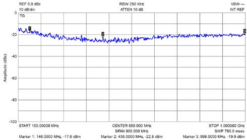
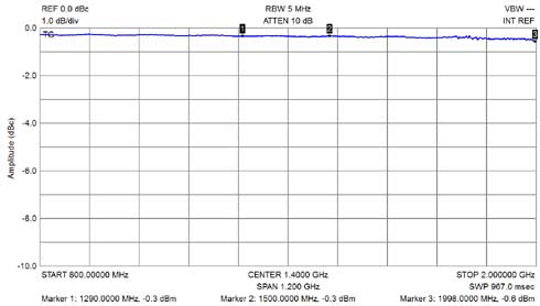
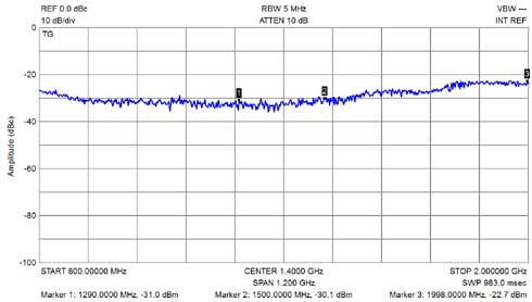
- EME181 Performance Tests:
- Mounting into a die cast enclosure:
- Kit changes and Updates:
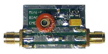
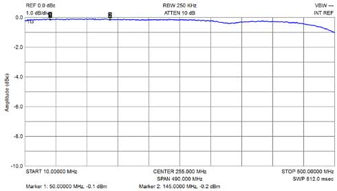
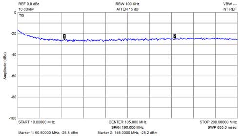
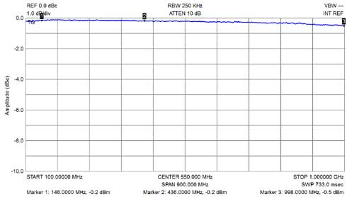
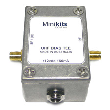
The EME181 Series RX bias tee Kits are suitable for powering Receive Preamplifiers from 50MHz to 1.2GHz via a coaxial cable. All Kits have been optimized to cover each specific band, for the lowest loss and return loss. Kits are available to cover the 6M ( 50MHz ), 2M (144MHz ), 70cm ( 430MHz ), and 23cm ( 1.2GHz ) bands. The EME181A70, 70cm version is recommended for wide band scanning receivers and will cover at least 50MHz to 2GHz.
The board is fitted with PTC protection to safeguard against any short circuits on the RF/DC output connection with a maximum DC voltage and current of +25vdc @ 160mA. The design uses inductors wound using Toroids that have been optimized for the lowest RF return loss across the bands.
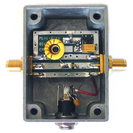
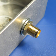
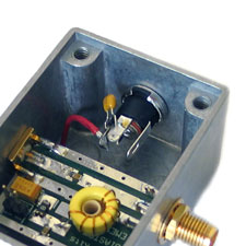
There can be some variations with connectors, and mounting hardware thicknesses that may require some experimentation when mounting boards into enclosures. Recently some SMA panel mount connectors may require additional washers due to the female thread not going all the way to the mounting flange. Many of the shake proof washers that are being supplied with SMA connectors are very flimsy and easily deform when tightening, so one picture above shows the use of a M6 shake proof washer that were used to securely hold the SMA connector to the enclosure.
-
Construct the PC board as per the EME181 Kit construction notes but DO NOT fit the SMA connectors to the board.
-
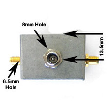
Carefully mark and drill the two 6.5mm, ( 1/4" ) and single 8mm holes in the die cast enclosure as shown in the picture above.
-
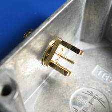
Loosely fit the two SMA connectors to the enclosure in a position that will allow the PC board to be slid between the guides on the rear of the connectors.
-
Turn the PC board and SMA connectors in the enclosure until the board sits in its normal horizontal position. Tighten the SMA connectors firmly, and then align the connector pins carefully with the PC board strip lines.
-
Solder the top of the PC board to the two SMA connectors, and then loosen the nuts on the connectors and rotate the board 180 degrees in the enclosure. Solder the SMA connectors to the bottom ground plane side of the board.
-
Connect a wire from the DC input of the board that can then be soldered to the DC socket for power.
-
Realign the PC board in the enclosure in its final position, and then firmly tighten both nuts on the SMA connectors.
-
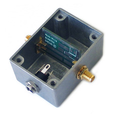
Fit the 2.1mm DC socket to the enclosure along with a 10nF capacitor. Solder the wire that was connected to the PC board to the DC connection lug on the rear of the DC socket. The wire should be routed under the board so that it does not affect the RF operation of the circuit.
-
This concludes the construction of the complete boxed Kit which can now be tested.
-
Please note that when tightening up the nuts on the SMA connectorsr, be careful not to twist the PC board which could crack the smd components. When connecting cables to the sockets, only do up hand tight to avoid twisting the connectors that could place strain and twist the PC board.

