EME179 Preamplifier Kits
- EME179-23CM Description:
Updated! Oct 2023 - Kit Constructors Alert:
Updated! Sep 2019 - EME179-23CM-R1 Kit Notes:
Discontinued - EME179-23CM-R2 Kit Notes:
- Mounting In A Die cast Enclosure:
- EME179-23CM Kit Performance Tests:
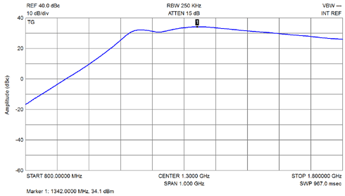
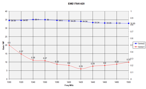
- EME179-1420 Performance Tests:
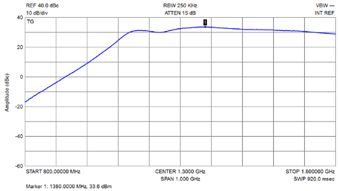
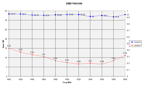
- EME179-1540 Performance Tests:
- Kit changes and Updates:
Updated! June 2024 - Buy A EME179-23CM Series Kit:
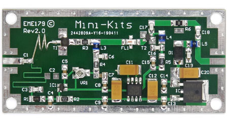
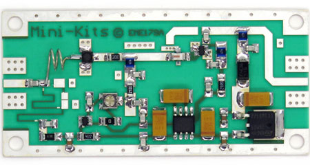
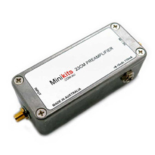
The EME179 Series Kits are high performance low noise receive only Pre-amplifier kits suitable for many Ham Radio applications to improve weak signals due to either high coaxial cable losses, or a low gain receiver. Kits and fully constructed products are currently available for the 1290MHz ( 23cm band ), and the 1420 and 1540MHz bands. Many commercially produced 23cm Transceiver and Receivers may have very low Noise figure Gas FET front ends, but generally lack enough gain in the receiver to comfortably listen to weaker narrow band signals like SSB or CW. The 23cm Pre-amplifier Kit is also particularly suitable for improving Amateur Television pictures, and is supplied with details to re-tune it for use on the 1420MHz/1540MHz bands.
The EME179-23CM-Rev1 has been updated to EME179-23CM-Rev2 in May 2019 due to component availability and to reduce the cost by changing to FR4 PC board material.
Currently no 13cm version is available as we have had issues with the design of the input circuit that appears to not be suitable for producing a low noise figure and good input return loss.
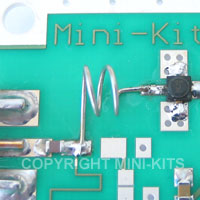
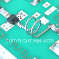
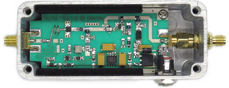
1/ October 2015, Built products are now fitted with a 2.1mm DC socket and 1N4007 diode for the external power connection. The DC connector makes it much easier to connect DC power and the diode provides reverse polarity protection to the circuitry. See the pictures below for the change to this product.
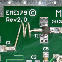
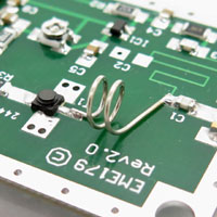
This Kit is for advanced constructors due to the very small SMD components which are unavoidable for stable consistent performance. The Pre-amplifier can be tuned for lowest noise figure between 1180 to 1500MHz, and is suitable for FM or SSB applications including Satellite and ATV reception. The design is essentially broadband, which uses a very low noise 0.35dB @ 12GHz CE3512K2 HJ FET input amplifier, followed by a low noise PSA-0012 GaAs MMIC. The Pre-amplifier can be used on either a 50 or 75ohm antenna, or coaxial cable systems. BUY THIS PRODUCT
This Kit is for advanced constructors due to the very small SMD
components which are unavoidable due to many older components
becoming obsolete. The pre-amplifier can be tuned for lowest noise
figure between 1180 to 1500MHz, and is suitable for FM or SSB
applications including Satellite and ATV reception. The design is
essentially broadband, which uses a very low noise 0.35dB @ 12GHz
NE3512S02 HJ FET input amplifier, followed by a low noise MGA82563
GaAs MMIC. The pre-amplifier can be used on either a 50 or 75ohm
antenna, or coaxial cable systems.
There can be some variations with connectors, and mounting hardware thicknesses that may require some experimentation when mounting boards into enclosures. Recently some SMA panel mount connectors may require additional washers due to the female thread not going all the way to the mounting flange. Many of the shake proof washers that are being supplied with SMA connectors are very flimsy and easily deform when tightening, so one picture above shows the use of a M6 shake proof washer that was used to securely hold the SMA connector to the enclosure.
-
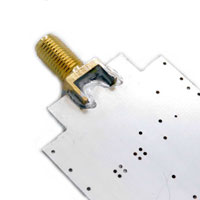
Cut out the two corners of the PC board near the RF input connector using a nibbling tool.
-
Solder an extended SMA female connector with washer and nut ( SMA49 ), to the input of the PC board making sure that it sits at the same angle as the sloped sides of the Hammond 1590A enclosure. Take your time here to make sure that the sma connector is close to the angle of the enclosure so that when it is tightened up the PCB, is parallel to the bottom of the enclosure. Then solder the connector on the bottom ground plane side of the board as shown in the picture above filling the gaps with solder.
-
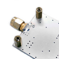
Solder the ( SMA50 ) Male PCB connector to the top of the PCB making sure that it is at right angles to the board. See the picture above to see how it is then soldered to the bottom ground plane of the PCB.
-
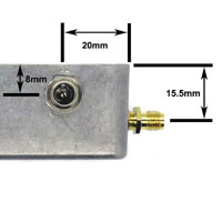
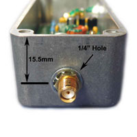
Mark and drill the two 1/4 inch holes in the die cast enclosure as shown in the picture above. If you are fitting the optional 2.1mm DC connector, then also mark and drill a 8mm hole to suit.
-
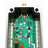
Near the input of the PC board cut the corners away using a nibbling tool so that they clear the corners of the enclosure. Refer to the picture above on how this is done.
-
Fit two M3x8 mm metal spacers using two M3x6 mm screws and washers to the output end of the board. This provides some extra stability to avoid twisting of the PC board.
-
Fabricate some stiff foam to fit under the PC board to provide extra stability to the board from twisting. The foam should be around 9mm thick so that it compresses slightly adding further stiffness when the board is fitted. A sharp scalpel knife is used to accurately cut the foam to size.
-
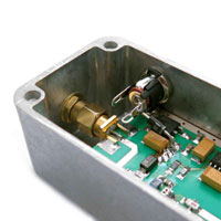
Fit a extended SMA female to female bulkhead mount ( SMA42 ) through one end of the enclosure, and screw a nut and washer on only by couple threads to allow enough clearance to then get the PC board into the enclosure. Refer to the picture above on how two nuts and a washer are used to take up the clearance on the outside of the enclosure.
-
Slide the PC board into the enclosure onto the foam, and pass the input sma connector through the hole in the enclosure. Next fit the shake proof washer and tighten the SMA nut on the input SMA avoiding twisting the PC board to hold it into place.
-
Next Lightly tightened up the output SMA50 male to the SMA42 adaptor as shown above. Some care is required here to not place stress on the SMA connectors or PC board.
It is very easy to twist the PCB which could damage components or rip the SMA connecter from the end of the board. -
Fit the 2.1mm DC connector to the enclosure and rotate it and tighten the nut as shown in the picture above. Fit the 1N4007 diode as shown in the picture to protect the preamp from reverse polarity.
-
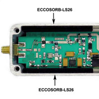
Glue some black antistatic foam to the lid of the enclosure using hot melt glue. Stick the two supplied strips of Eccosorb LS-26 material along the sides of the board to reduce the enclosures resonances.
-
Finally adjust the bias to 10mA and fully test test the Pre-amplifier.
-
Place the lid onto the enclosure and check that the Pre-amplifier is stable and does not oscillate.
1/ The EME179-23CM-Rev1 has been updated to EME179-23CM-Rev2.0 in May 2019 due to component availability and to reduce the cost by changing to FR4 PC board material.
2/ Due to obsolescence the MGA82563 has been replaced with the PSA-0012 in Rev2.1 Kits. The only change is to replace the 24R resistor with a 10R.
3/ The 100ohm bias trim pot has no effect and the 10mA current cannot be set. The common cause is a solder bridge between pins 3 and 4 of the BCR400W.
4/ A faulty 100ohm Trim pot was found on one of the Kits that did not allow the bias to be set. It was internally leaky and measured around 8 ohms.
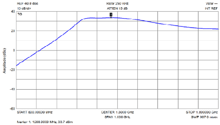
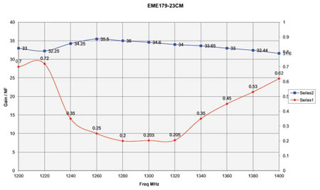
5/ Poor frequency response at 1240 to 1300MHz and gain less than 30dB. Check that the HFCN-1200 filter has been fully soldered to the board. There are ground connections on the sides of the filter that also need soldering. If it is soldered fully, then the filter is probably faulty or has been damaged when soldering. This fault has now been seen on a number of Pre-amplifiers so should be checked if gain is down.
6/ Low gain can be due to the 10nF capacitor at the junction of the 47ohm and 4k7 resistors not being soldered on one end.
7/ Low gain can also be due to the Low noise NEC FET or MGA82563 being damaged due to RF or static. Check the voltages and current for both devices using the circuit diagram supplied with the Kit notes
8/ Poor frequency response and a very high peak at around 1200MHz could be due to oscillation caused by the input SMA connectors pin being shorted across the connector to ground.

