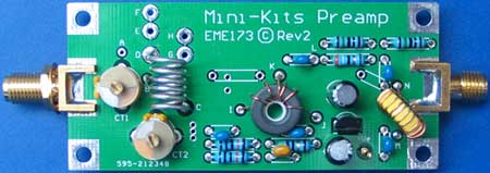
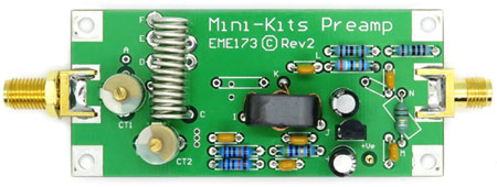
EME173-Rev2 Preamplifier Kits
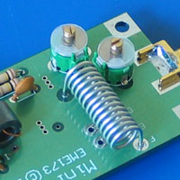
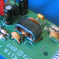
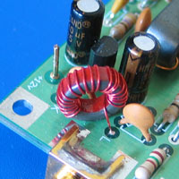
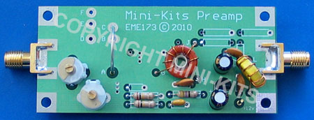
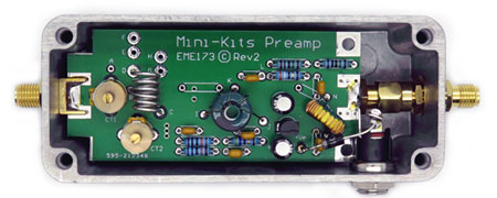
The EME173 PC board was updated in January 2015 to improve the input matching circuit for a lower noise figure. The board was designed to suit the construction of receive only preamplifiers for the 30 to 500MHz bands. All Kits use the low cost BF998 MesFET from NXP that has a low noise figure and were designed for television tuners. The output of the BF998 is matched to 50ohms using a tapped transformer ensuring stable operation. The preamplifiers can all be adapted for frequencies outside the ranges specified for each product, by simply changing the turns on the input inductor. The upper range of the EME173-70CM Kit however is around 500MHz maximum.
Due to the availability of film trimmer capacitors, the Rev2 Kits are slowly being replaced with the Rev3 PC board. There are no other changes to the circuit.
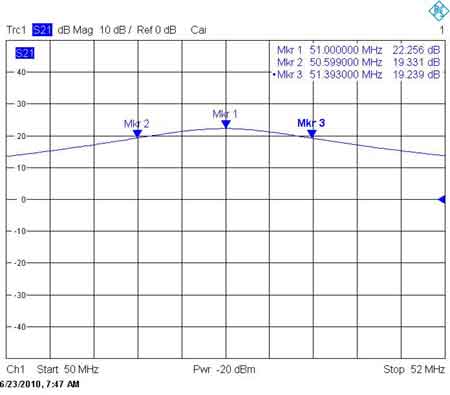
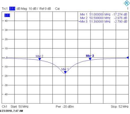
The Preamplifier has been designed to be easy to construct, and can be centre frequency tuned for use between 45 and 65MHz, and is suitable for the 50-54MHz Amateur Band. A low cost BF998 MesFET has been used as it has very good characteristics on the VHF to UHF bands. The BF998 was specifically designed for television tuners, and has a low 0.7dB NF at 50MHz along with high cross modulation performance. The BF998 incorporates integrated gate input protection diodes to help prevent damage to the device from static. The Preamplifier design is essentially a tuned input MesFET, with a wide band 50ohm matching transformer on the output. The Preamplifier however can also be used on a 75ohm antenna, or coaxial cable systems. BUY THIS PRODUCT
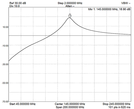
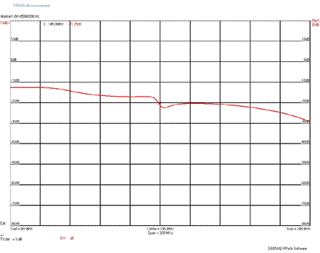
The Preamplifier has been designed to be easy to construct, and can be centre frequency tuned for use between 115 and 180MHz, and is suitable for the 144-148MHz Amateur Band. A low cost BF998 MesFET has been used as it has very good characteristics on the VHF to UHF bands. The BF998 was specifically designed for television tuners, and has a low 0.7dB NF at 145MHz along with high cross modulation performance. The BF998 incorporates integrated gate input protection diodes to help prevent damage to the device from static. The Preamplifier design is essentially a tuned input MesFET, with a wide band 50ohm matching transformer on the output. The Preamplifier however can also be used on a 75ohm antenna, or coaxial cable systems.
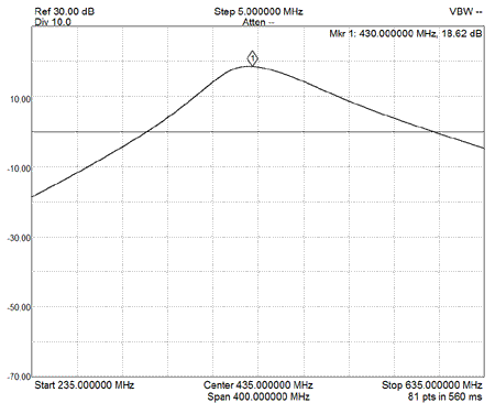
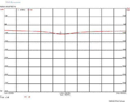
The Preamplifier has been designed to be easy to construct, and can be centre frequency tuned for use between 350 and 500MHz, and is suitable for the 430-450MHz Amateur Band. A low cost BF998 MesFET has been used as it has very good characteristics on the VHF to UHF bands. The BF998 was specifically designed for television tuners, and has a low noise 1dB NF at 435MHz along with high cross modulation performance. The BF998 incorporates integrated gate input protection diodes to help prevent damage to the device from static. The Preamplifier design is essentially a tuned input MesFET, with a wide band 50ohm matching transformer on the output. The Preamplifier however can also be used on a 75ohm antenna, or coaxial cable systems.
There can be some variations with connectors, and mounting hardware thicknesses that may require some experimentation when mounting boards into enclosures. Recently some SMA panel mount connectors may require additional washers due to the female thread not going all the way to the mounting flange. Many of the shake proof washers that are being supplied with SMA connectors are very flimsy and easily deform when tightening, so one picture above shows the use of a M6 shake proof washer that was used to securely hold the SMA connector to the enclosure.
-
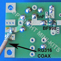
Solder an extended SMA female, ( SMA39 ) to the input of the PC board making sure that it is at right angles to the board. Take your time here to make sure that the SMA connectors on both the input and output of the preamp are straight in both planes.
-
The SMA12 male PCB connector will need modifying as it will not easily slide onto the RF output connection board. Modify the connector by breaking two diagonal tabs of the bottom of the flange to allow the connector to fit flat onto the top of the board. Solder the connector to the top of the PCB making sure that it is at right angles to the board. See the picture above to see how it is then soldered to the bottom ground plane of the PCB.
-
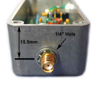
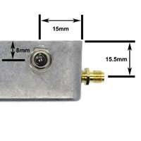
Mark and drill the two 1/4 inch holes in the die cast enclosure as shown in the picture above. If you are fitting the optional 2.1mm DC connector, then also mark and drill a 8mm hole to suit.
-
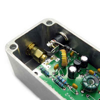
Near the input of the PC board cut the corners away using a nibbling tool so that they clear the corners of the enclosure. Refer to the picture above on how this is done.
-
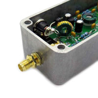
Fit a extended SMA female to female bulkhead mount ( SMA42 ) through one end of the enclosure and screw a nut and washer on only by couple threads to allow enough clearance to then get the preamp board into the enclosure. Refer to the picture above on how two nuts and a washer are used to take up the clearance on the outside of the box. Some experimentation with the washer may be required to fit the SMA42 adapter. Sometimes Mini-Kits mounts the washer inside the enclosure, or if its too tight a fit it is then mounted on the outside.
-
Slide the preamp board into the enclosure and pass the extended input SMA connector through the hole in the enclosure, and lightly screw on the SMA nut and washer to hold it into place. In many cases a M5 nickel steel shake proof washer maybe used to secure the connector better.
-
Lightly tightened up the output SMA male to the SMA bulkhead adapter.
-
Finally carefully tighten the input SMA nut using a suitable SMA spanner. Finally the nuts on the output SMA bulkhead adaptor can be tightened ensuring that there is not excessive stress placed on the board and connectors.
-
Fit the 2.1mm DC connector to the enclosure and rotate it and tighten the nut as shown in the picture above. Fit the 1N4007 diode as shown in the picture to protect the preamp from reverse polarity.

