M1 Series Modular Transceiver
- M1 Series HF Transceiver
Description:
Updated! Nov 2023 - M1 Transceiver Block
Diagram Rev1.6:
Updated! 13/3/17 - M1 Excel Price Calculator
Guide
Updated! Nov 2023 - EME201 10dB HF Amplifier Module:
Completed! - EME202 HF Mixer / Post Amplifier Module:
Updated! 31/7/17 - EME203 Crystal Filter Module:
SSB and CW Filter Updated 16/3/16! - EME204 9MHz I/F AGC Module:
Completed! - EME205 9MHz BFO / Demodulator Module:
Completed! - EME206 Audio Amplifier Module:
Completed! - EME207 Pre-selector Filter Modules:
Updated! 9/2/16 - EME208 Transmit Modulator Module:
Completed! - EME209 Low Pass Filters:
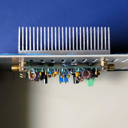
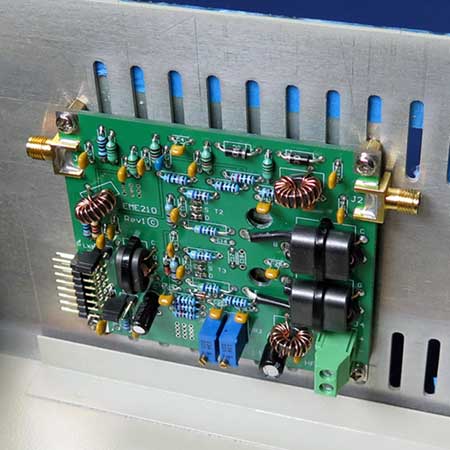
Completed 160 to 6M Bands - EME210 16W RF Amplifier Module:
Completed! - EME211 6/12/18dB Attenuator 9MHz Trap Module:
Completed! - EME212 RF Speech Processor Module:
Design Stage 1/12/15 - EME213 Noise Blanker Module:
Completed 25/5/17 - Fitting it all into an
Enclosure
Updated! 1/11/15 - M1 Front Panel
Updated! 16/6/22 - M1 DDS Controller Web page
Completed! - M1 Software development:
Updated! 12/1/16 - What other Components are
required:
Updated! - Changes and Modifications:
Updated! - Accidental Faults:
Updated! 14/2/16 - Buy M1 Series Module Kits:
The M1 Series HF Transceiver is a modular design using a number of module boards with 50 ohm RF connections, and a common 16 Pin IDC connector for logic control allowing easy plug and play, and experimentation of the modules. The design is a conventional analogue design using a single conversion 9MHz I/F, very similar to Transceivers that were manufactured in the late 1970's. Many of these Transceivers used narrow pre-selection filters, and quality crystal filters that are only used these days in higher priced Ham Transceivers.
The M1 design brings together the best analogue design techniques that have been used over many years, which have been re-engineered using modern components to improve the performance. Conventional leaded components have mainly been used to make construction easier, and SMD components have only been used where required to either improve performance, or if there was no alternative.
The M1 Receiver produces high quality low distortion audio which does not cause fatigue like lower cost modern transceivers that use DSP filtering. The receiver and transmit audio has that very nice Kenwood sound that is typical of Transceivers that use quality crystal filters. The Transmitter produces a very clean RF output due to extensive filtering and the use of Mitsubishi MosFETs in the PA, and many reports from other stations have commented on the excellent punchy audio that is very easy to listen to.
The M1 Transceiver block diagram shows how the various modules are connected together to construct the receiver, and only a Local Oscillator from 9 to 39MHz is required to feed into the Mixer for tuning the receiver. The functions of the M1 receiver can be easily controlled using analogue switches and simple logic, without the requirement of a micro controller. A dedicated M1 DDS Controller is now available to suit the M1, and can be used with either the AD9850/51 or AD9951/54 DDS chips for stable frequency and easy logic control of the M1 module functions.
Many of the modules shown in the M1 Transceiver block have a dual function, and also also used in the transmitter, these include the EME201, 202, 203, 205 and 207 Modules. There could be a number of other modules that maybe available later including, an optional receiver protection module that could also incorporate a SWR circuit, and there are plans to still complete the RF speech processor module.
For more information on each module, please refer to the Modules specific web page links at the top of this page.
The M1 Transceiver was not designed to be sold as a complete Kit, so we have produced an Excel Spread Sheet that can now be downloaded to help calculate what you might require including the costs to construct your own version of the M1 Transceiver. Due to limited hardware manufacturing in Australia, there are no plans to supply a complete enclosure or front panel assembly. The cost to produce anything like this in Australia is just not viable.
The Basic Module Kits include the IDC header connectors but do not include the 16 way 1.27mm ribbon cable, RF connectors, cable, or hardware. It is recommended that SMA connectors are used on the modules to make easy interconnection between the various boards, however RG316 or similar cable cable be directly soldered between the boards to keep costs lower. If you want to construct a simple analogue design without the M1 logic and micro controller, then you can use simple logic control using switches, and a 9 to 39MHz VFO oscillator for tuning.
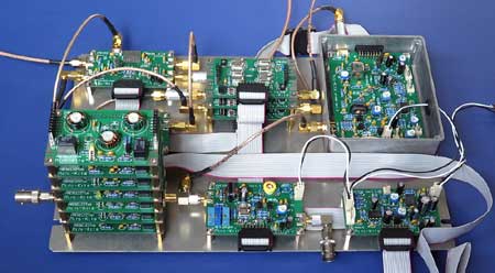
The picture below shows the modules that are currently available to construct the complete M1 Transceiver that covers all the HF Amateur Radio bands, ( Excluding the 30M Band ) from the BC Band to 30MHz. The modular design allows the constructor to only purchase filters for bands that are required to save on costs. A number of the modules shown have a dual function and are also used in the transmitter, and the addition of a SSB/CW modulator, RF power amplifier and low pass filter is all that is required to transmit on a single band.
A complete M1 DDS Controller solution
is now available, and will allow full control of the M1 modules
functions and power switching requirements. The HF-DDS software has
been modified to suit the M1 Transceiver functions, and can be used
with either the AD9850/51 or AD9954 DDS chips. The M1 DDS controller
directly interfaces with the Mini-Kits AD9851 or AD9951/54 DDS Kits,
but for the best performance the AD9951-54 is recommended as it
produces very low birdies that generally cannot be heard when tuning
across quiet bands.
1/ \ I understand that there are many constructors that are waiting to see how the complete hardware all comes together and to see a final product. An Excel calculator can now be downloaded to guide constructors on what might be required including the costs.
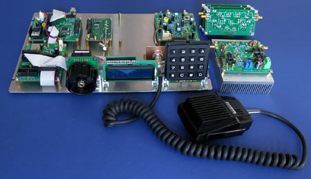
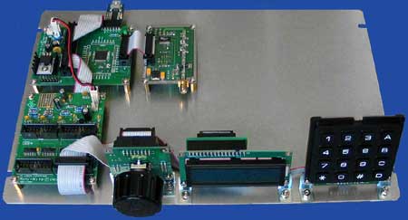
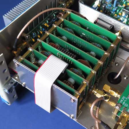
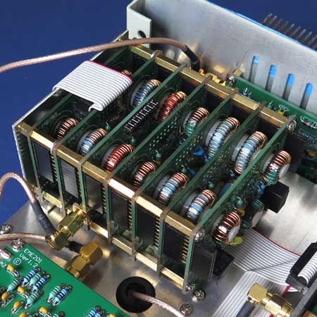
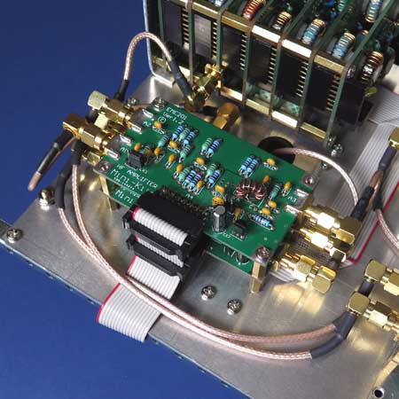
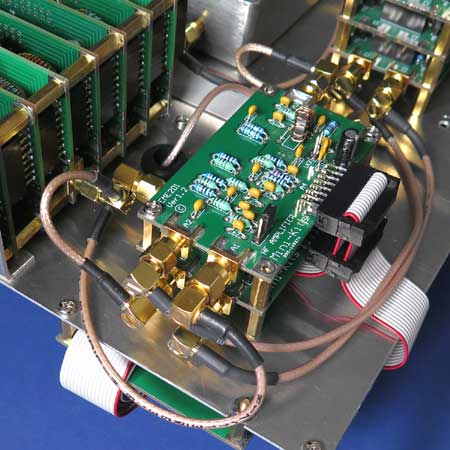
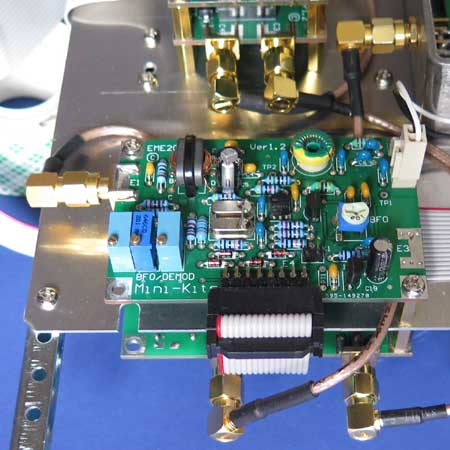
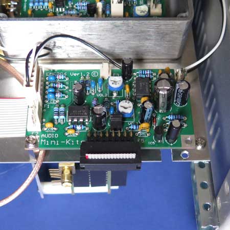
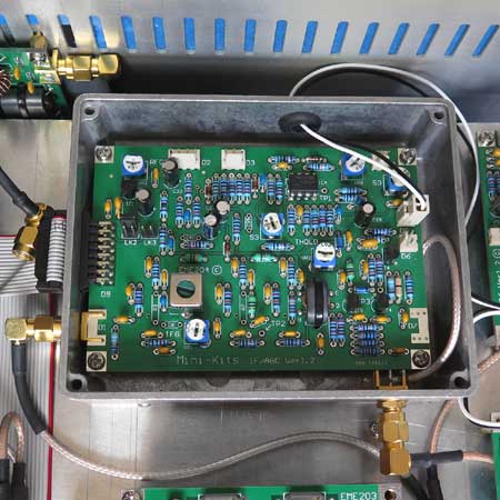
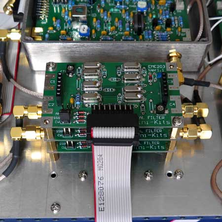
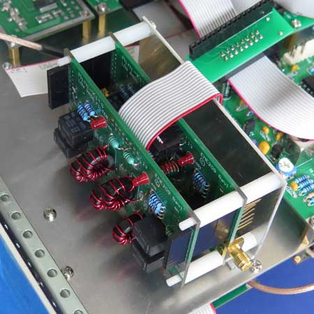
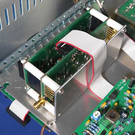
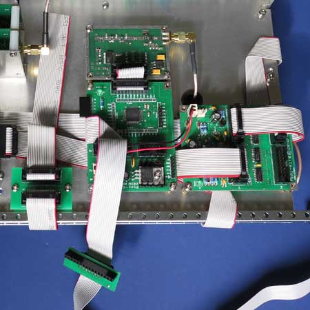
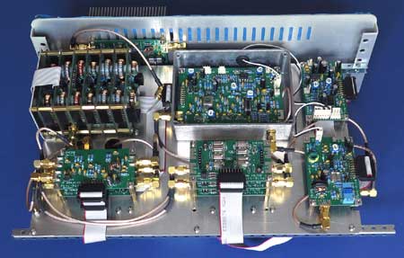
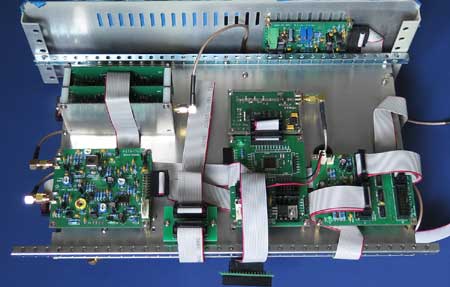
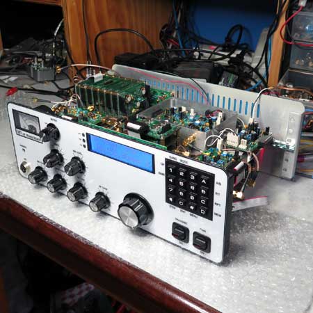
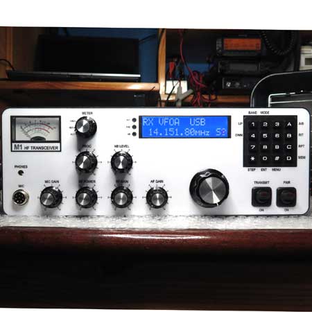
It is important to layout the modules logically with regards to the distances required between the modules and other hardware like the S-meter and potentiometers etc that might require clearance inside the enclosure. You also need to take into account with keeping any high gain RF stages away from lower level RF stages and also keeping the micro-controller and DDS away from the receiver. As the pictures shop below, the mounting of the boards into the enclosure has finally started. Most of the receiver circuitry has been mounted onto the top of an aluminium chassis giving plenty of clearance around the modules for cable wiring.
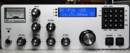
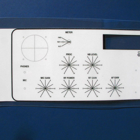
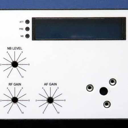
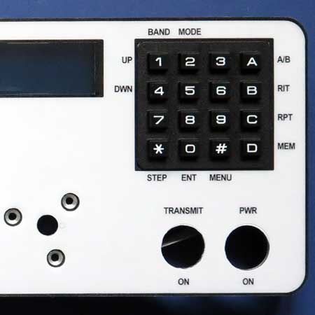
It was decided to try using a thick laminate to create a front panel which can easily be updated at low cost if something needs to be changed. A full size prototype front panel can be downloaded here in PDF format or in Autosketch format, and below is the prototype panel using 300 x 2 micron laminate on thick paper. The results so far are very pleasing, and allows easy changes to the front panel which are low cost compared to screen printing. The paper was cut out for the LCD display which makes a very nice clear laminate window.
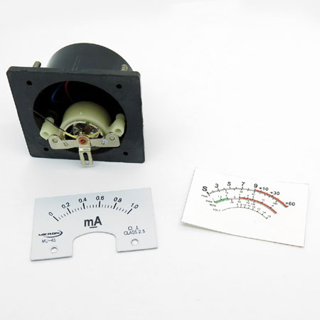
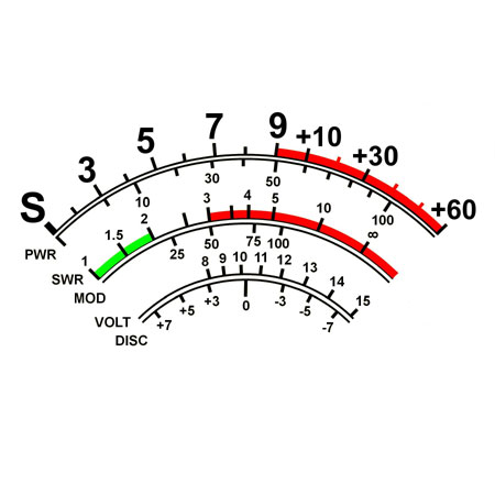
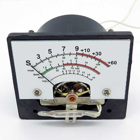
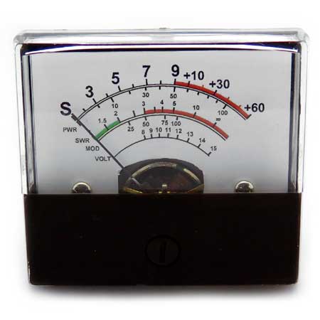
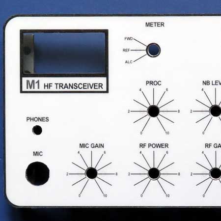 This picture shows how the transparent window for the S meter looks. The window was cut out of the paper using a sharp scalpel before the paper was laminated. Most holes were punched out using metal hole punches after laminating, and before the laminated sheet was glued to the aluminium panel. Dabs of Bostic Multibond glue was used to stick the laminated sheet.
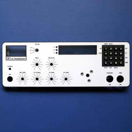 There is quite a lot of work to get to this stage, so any mistakes along the way would mean starting all over again. The whole process of cutting out the paper etc before laminating to get the s-meter and LCD windows, and then punching out holes for the controls etc has to be made in the correct order.
1/ There are a number of changes to some modules that can be found on the module specific web pages to fix mostly minor problems that have been found. There will always be some changes and improvements found over time which is even common with the major manufacturer brands.
2/ There have been changes to the Transceiver Block Diagram to fix mistakes with the RF connections for the Crystal Filter Module, and also additions of the new modules available.
1/ Oops I shorted out the 16 way ribbon cable that connects to the crystal filter modules. This caused the +12vdc to pin 15 of a number of modules to be not present, including the audio amplifier so there was no sound from the speaker. The fault was tracked down to a burned track on one of the EME186 IDC adaptor boards that I used. The track was open circuit so acted like a fuse and is between pins 16 of each female header. This is probably a good safeguard so make sure that you use some thin wire when repairing tracks.

