EME236 Series Return Loss Bridges

Please Note: that all information including pictures on this web page are copyright to Mini-Kits and must not be used on any other web site, or reproduced in any publication.

EME236 PC Board Description:

The EME236 PC board was released in January 2018 and was designed to construct RF couplers and Return Loss Bridges ( RLB ), and RF Couplers for the HF to UHF Bands. A RLB is used to evaluate an impedance match to 50ohms, so can be used to evaluate the input or output impedance of amplifiers and filters, and antenna impedances. An RLB is normally used with other test equipment like a VNA or spectrum analyzer and tracking generator.

Not all products are available as Kits as the board was specifically designed to suit a packaged pre-built product. The board is also used for a number of other products including receive only Bias Tee's, ( DC Power Injectors ).

Currently Mini-Kits produces a EME236-ADC-20-4 Return Loss Bridge that covers 0.5MHz to 1GHz which is available as a built module only.

EME235-RLB-0.5M500 Product Notes:

The EME235-RLB-0.5M500 Return Loss Bridge has a usable frequency range from 0.5 to 200MHz for a better than 20dB coupling. The tests below show that around 8 turns is the best compromise for a flat response and operation up to 500MHz with a 20dB return loss. The RLB can be used with a VNA or spectrum analyzer and tracking generator to tune RF filters and check Antennas. The tests below may vary depending on the spacings of the turns on the toroid, so some experimentation may be required with spreading or compressing the turns around the toroid to optimize. This Product has never been produced

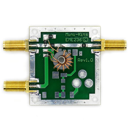
  • EME235RLB-0.5M200 PCB Top View
    The picture shows the EME235-RLB-0.5M200 Return Loss Bridge with SMA connectors. The RLB is only available with SMA Female connectors for accurate performance.
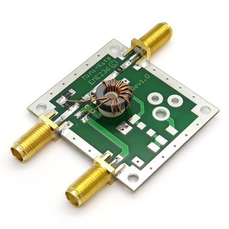
  • EME235RLB-0.5M200 Angled View
    The picture shows the EME235-RLB-0.5M200 Return Loss Bridge with another view to show the Toroid connections to the PC board. Construction is not critical but the turns should be evenly spaced.
  • EME236-RLB-FT37-75-7T
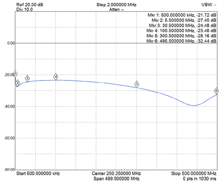
    EME236-RLB-0.5M500 Shows the Detector output with a 50ohm termination on the RF output when using 6 bifilar turns on a FT37-75 Toroid. Performs better at high frequencies over 300MHz and has >23dB directivity at 100MHz
  • EME236-RLB-FT37-75-10T
    EME236-RLB-0.5M500 Shows the Detector output with a 50ohm termination on the RF output when using 7 bifilar turns on a FT37-75 Toroid. This RLB is good all the way from LF to at least 300MHz with a >25dB directivity.
  • EME236-RLB-FT37-75-7T
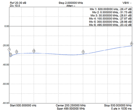
    EME236-RLB-0.5M500 Shows the Detector output with a 50ohm termination on the RF output when using 8 bifilar turns on a FT37-75 Toroid. Has a flatter lower frequency response with a upper frequency of around 300MHz for >27dB directivity
  • EME236-RLB-FT37-75-10T
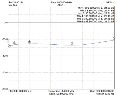
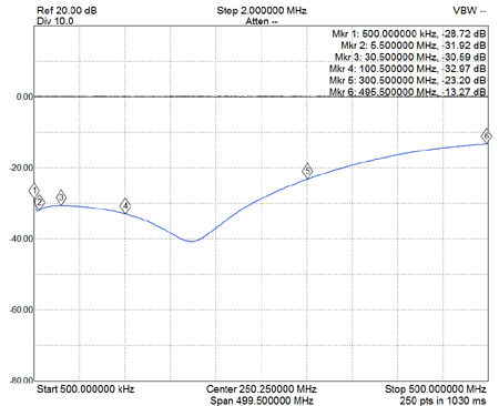
    EME236-RLB-0.5M500 Shows the Detector output with a 50ohm termination on the RF output when using 10 bifilar turns on a FT37-75 Toroid. Probably shows that 10 turns is excessive but would work well from LF to around 200MHz with a >30dB directivity
EME235-ADC-20-4 Product Notes:

The EME235-RLB-ADC-20-4 Return Loss Bridge uses a Minicircuits 20dB coupler, and has a usable frequency range from 0.5MHz to 1GHz. The RLB can be used with a VNA or spectrum analyzer and tracking generator to check the return loss and test input and output impedances of amplifiers and tune RF filters and Antennas. This product is only available as a packaged pre-built module. BUY THIS PRODUCT

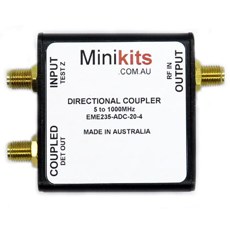
  • EME235-ADC-20-4 PCB Top View
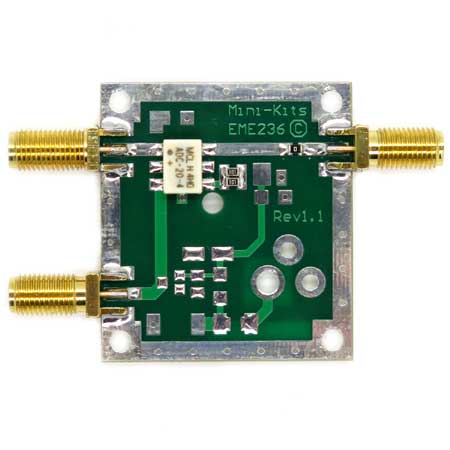
    The picture shows the EME235-ADC-20-4 Return Loss Bridge with SMA connectors. The RLB is only available with SMA Female connectors for accurate performance.
  • EME236-ADC-20-4-Plot5
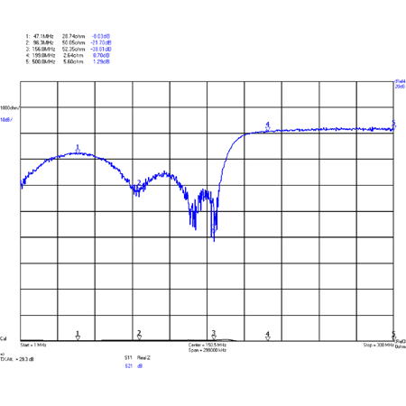
    The picture shows a 170MHz low pass filter being tested for return loss after calibrating the DG8SAQ VNA with the RLB inline for 0dB.
  • EME236-ADC-20-4-Plot1
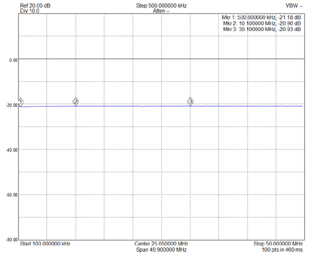
    EME236-ADC-20-4 Shows the actual loss of the board and RLB from 100kHz to 50MHz from the -20dB Coupled output ( Pin 3 ) to the Input Pin 1.
  • EME236-ADC-20-4-Plot2
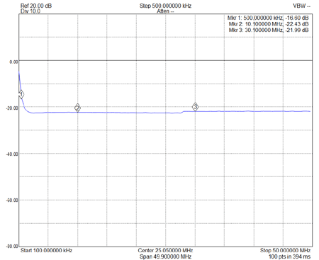
    EME236-ADC-20-4 Shows the -20dB Coupled output ( Pin 3 ) when a 50ohm load is placed onto the Input Pin 1. The RLB was first calibrated to 0dB spectrum analyzer and tracking generator.
  • EME236-ADC-20-4-Plot3
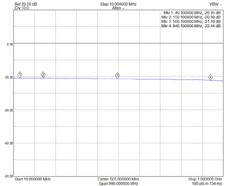
    EME236-ADC-20-4 Shows the actual loss of the board and RLB from 10MHz to 1GHz from the -20dB Coupled output ( Pin 3 ) to the Input Pin 1.
  • EME236-ADC-20-4-Plot4
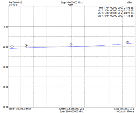
    EME236-ADC-20-4 Shows the -20dB Coupled output ( Pin 3 ) when a 50ohm load is placed onto the Input Pin 1. The RLB was first calibrated to 0dB spectrum analyzer and tracking generator.
Product Changes and Updates:

EME236-RLB-0.5M200

1/ There are no current updates to this product.

EME236-ADC-20-4

1/ There are no current updates to this product.