EME187 M1 Logic Board
- EME187 Logic Board Description:
Updated! June 2022 - EME187 Logic Rev1.2 Circuit
Diagram:
- Kit Constructors Alert:
- EME187 Construction Notes:
- M1 Functions Menu 6 Settings:
- Kit changes and Updates:
Updated! Dec 2015 - M1 DDS Controller Web page:
- M1 DDS Controller Block
Diagram:
- Matching EME190 Micro controller Board:
- Buy a EME187 M1 Logic Kit:
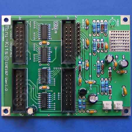
The EME187 Logic board has been designed as an interface between the EME190 micro controller board and the M1 Transceiver modules. The board expands the number of outputs from the micro controller for controlling the various functions of the transceiver, and also has onboard power supply switching to control the receive and transmit switching voltage requirements of the M1 Transceiver modules. When used with the EME190 micro controller board, 74HC595 expander IC's are used and provide up to 30 output functions that can be programmed with the M1-DDS software via a menu system. Please refer to the M1 Logic Control Block on how this board interfaces with the M1 Transceiver.
The EME187 Logic board circuit diagram is now available for download for those constructors that want to construct their own logic to control the M1 Transceiver modules. The circuitry shows how the power switching and other logic is handled for the various functions.
16 Pin IDC headers and ribbon cable are used for easy interconnection to the EME190 Microcontroller board and the M1 modules. The EME187 Logic board can be stacked on top of the EME190 Microcontroller board if required to save space. The onboard power supply was designed to suit the M1 Logic Control requirements. The maximum current is limited to under 200mA using an onboard PTC for protection, which is enough to power the board including the various switched voltage outputs for switching the power for receive and transmit etc to the M1 modules. Due to the minimal heat sinking on the +8v regulator, the maximum current on the +8v supply should be kept under 200mA.
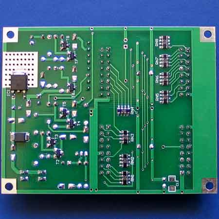
The construction is quite straight forward and many of the SMD components are easily fitted with tweezers. The Kit construction notes and overlay diagrams should be carefully followed when constructing. For larger pictures to check orientation of some components click the images below. Remember to fit the wire link to the deviation trim pot under the board. BUY THIS PRODUCT
The M1-DDS software has an LCD menu system for setting the output functions for the M1 Logic board. To enter the menu mode hold the # key on the keypad until the screen shows Setup Menu. Turn the rotary encoder until the display shows Menu 5 ( I/O Board Setup ) From there set the Output functions as per the current setting for the M1 Transceiver.
Current M1 Software Ver 1.L I/O Board Menu 6 Settings Download
1/ Most issues that have been found are on the M1 DDS Controller webpage.
2/ There is an issue with some Kits that when powered up continuously reboot the microcontroller. This is because they have been supplied with a RXEF010 PTC which should be a RXEF040. Please email Mini-Kits so that we can send you the correct RXEF040 PTC.
3/ One particular Kit that had the HF-DDS software programmed had the top row of the LCD module lit with square blocks only. There was no display on the bottom row. The fault was caused by a poor +12vdc power connection to the board arching to ground. The fault was traced to the LCD module that had been destroyed.


