EME178 PA Module Kits
- EME178 Description:
Updated! June 2022
- Kit Constructors Alert:
Updated! 24/7/18 - RA07H4047M KIT Construction Notes:
Updated! 4/10/22 - RA08H1317M KIT Construction Notes:
- Kit Changes and Repairs:
Updated! 19/8/18 - Buy A
EME178 Kit:
The EME178 PC board suits all the current low power VHF and UHF RA series Mitsubishi RF power modules. Mini-kits specifically has two Kits to suit the 2m 144-148MHz, and 430-450MHz bands. The Amplifiers are suitable for all modes including AM, FM and linear SSB. For SSB use the power output to use in linear operation is around half the power rating of the module.
1/ Refer to the Kit changes and Updates section for possible issues with setting the bias when using supply voltages from +12 to +13.8vdc.
1/ Refer to the Kit changes and Updates section for possible issues with setting the bias when using supply voltages from +12 to +13.8vdc.
For the latest service bulletins and data sheets, please see the Mitsubishi Semiconductors website.
- Conclusion of Substrate Crack Page 1-2
- Conclusion of Substrate Crack Page 3-14
- ROHS Compliance for RA and RD Series Modules
- Application Note Thermal Compound Mitsubishi Application Notes
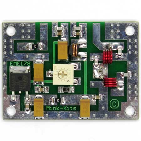
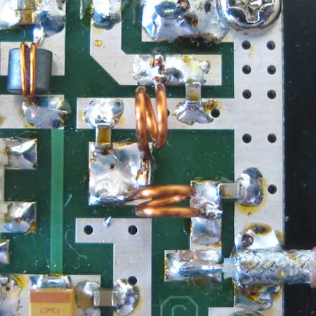
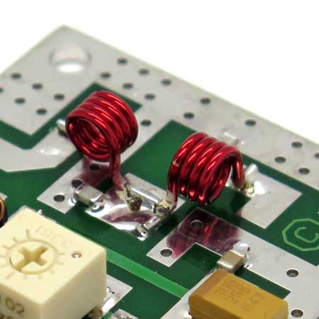
The pictures below show the basic constructed module board without the module fitted. The Kit construction notes and overlay diagrams should be carefully followed when constructing. For larger pictures to check orientation of some components, click the images below. Construction is quite straight forward and the only tricky part is the winding of the small coils. There should be no alignment required to the low pass filter coils if it is constructed carefully. The low pass filter has a 1dB cutoff of 450MHz, so will need changing if this product is used above 450MHz. This may require the capacitors or coils to be changed to different values. BUY THIS PRODUCT
The pictures below show the basic constructed module board without the module fitted. The Kit construction notes and overlay diagrams should be carefully followed when constructing. For larger pictures to check orientation of some components click the images below. Construction is quite straight forward and the only tricky part is the winding of the small coils. There should be no alignment required to the low pass filter coils if it is constructed careful. BUY THIS PRODUCT
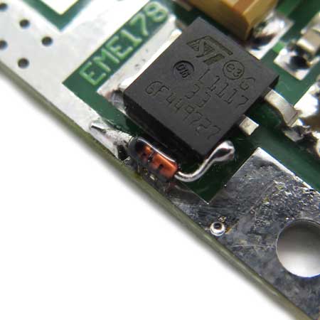
1/ There is a possibility that the bias when adjusted to the
maximum voltage of +3.3v is not enough to make the module drain
current high enough to allow the module to produce the full RF
output power. This could be due to using a +12vdc supply which may
require a higher bias voltage around +3.5vdc compared to using a
+13.8vdc supply that requires a lower gate voltage nominally around
+3vdc. In this case a series 1N4148 diode can be fitted in series
with the 3v3 regulators ground pin to the PCB ground connection
which should lift the voltage from the regulator to around 4v
maximum allowing the bias to be set.


